


8 9
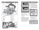
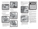
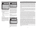
3. Hold the front of the shoe and rotate the
saw by the handle to the desired angle
as indicated by the markings on the
bevel scale (Fig. 7).
4. Tighten the bevel adjusting knob se-
curely.
Fig. 7
5. Place the blade fl ange on the spindle
and hand tighten the bolt.
6. While holding the spindle lock button in,
use the wrench to turn the bolt counter-
clockwise and tighten.
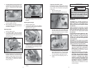
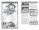
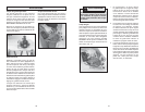
4. To install a blade, place the blade on the
spindle with the teeth pointing in the same
direction as the arrow on the lower guard
(Fig. 3). Release the lower guard
lever.
Adjusting Depth
1. Remove battery pack.
2. To adjust the depth of the cut, hold the
saw by the handle and loosen the depth
adjusting lever by pushing it down toward
the shoe (Fig. 4).
4. Lift the depth adjusting lever up towards
the motor housing to secure the shoe
position.
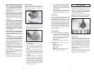
Adjusting Bevel Angle
1. Remove battery pack.
2. To adjust the angle of the cut, hold the
saw by the handle and loosen the bevel
adjusting knob. (Fig. 6).
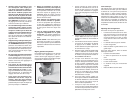
3. Raise or lower the shoe to the desired
position. Markings in 1/4" increments are
located on the inner side of the upper
guard for depth setting. For the proper
depth setting, the blade should extend
no more than 1/4" below the material
being cut (Fig. 5).
Fig. 6
Fig. 3
Fig. 4
1/4"
Fig. 5
WARNING
OPERATION
To reduce the risk of injury, keep hands
away from the blade and other moving
parts. Always wear safety goggles or
glasses with side shields. Use only
specifi cally recommended accesso-
ries. Others may be hazardous.
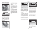
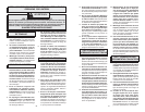
3. To make sure the blade is 90 degrees to
the shoe, place saw on the blade side
and retract lower guard. Place a square
against the blade and shoe to inspect
the degree setting (Fig. 9).
Adjusting the Blade to Shoe
The shoe has been adjusted at the factory
to a 90 degree setting. Inspect the saw regu-
larly to make sure the blade is 90 degrees
to the shoe.
1. Remove battery pack.
2. Set the bevel pointer to zero (Fig. 8).
4. To adjust the degree setting, loosen the
bevel adjusting knob. Turn the bevel
adjustment screw in or out until the blade
is at a 90 degree angle with the shoe.
5. Tighten the bevel adjusting knob se-
curely.
Fig. 9
Bevel adjustment screw
Fig. 8
Causes and Operator Prevention of
KICKBACK:
KICKBACK is a sudden reaction to
a pinched, bound or misaligned saw
blade, causing an uncontrolled saw to
lift up and out of the workpiece toward
the operator.
When the blade is pinched or bound
tightly by the kerf, or cutting slot, closing
down, the blade stalls and the motor reac-
tion drives the unit rapidly back toward
the operator.
If the blade becomes twisted or mis-
aligned in the cut, the teeth at the back
edge of the blade can dig into the top
surface of the wood causing the blade
to climb out of the kerf and jump back
toward operator.
KICKBACK is the result of tool misuse
and/or incorrect operating procedures or
conditions and can be avoided by taking
proper precautions as given below:
1. Maintain a fi rm grip with both hands
on the saw and position your body
and arm to allow you to resist KICK-
BACK forces. KICKBACK forces can
be controlled by the operator, if proper
precautions are taken.
2. When blade is binding, or when inter-
rupting a cut for any reason, release
the trigger and hold the saw motion-
less in the material until the blade
comes to a complete stop. Never
attempt to remove the saw from the
work or pull the saw backward while
the blade is in motion or KICKBACK
may occur. Investigate and take cor-
rective actions to eliminate the cause
of blade binding.