


page 6
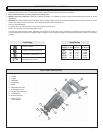
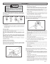
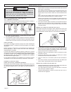
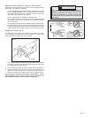
Adjustable Pivot Shoe (Fig. 4)
The shoe can be adjusted forward or backward to three positions to
take advantage of the unused portion of the blade or for special jobs
requiring low blade clearance.
1. To adjust the shoe, pull the shoe release lever down 1/4 turn and
slide the shoe forward or backward to the desired position.
2. To lock the shoe in position, push the shoe release lever up.
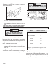
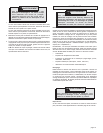
3. After adjusting the shoe, slowly pull the trigger to be sure the blade
always extends beyond the shoe and your work throughout the
stroke.
DO NOT OPERATE SAWZALL WITHOUT SHOE. STRIKING THE SPINDLE
AGAINST WORK MAY DAMAGE THE RECIPROCATING MECHANISM.
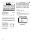
WARNING!
To reduce the risk of injury, be sure the blade
always extends beyond the shoe and work
throughout the stroke. (Fig. 5) Blades may shat-
ter if they impact the work or shoe.
1/4 Turn
Fig. 4
Trigger Speed Control Switch
Super Sawzalls
®
are equipped with a trigger speed control switch. It
may be operated at any speed from zero strokes per minute to full
speed. Always start tool before blade contacts the workpiece. To vary
the speed, simply increase or decrease the pressure on the trigger. The
further the trigger is pulled, the greater the speed. To stop the tool,
release the trigger and allow the tool to stop completely before removing
from a partial cut or before laying the tool down.
OPERATION
Impact Protection System
Select models are equipped with a unique patented gearing system that
provides efficient power transmission and extended life in the most
difficult cutting applications. This durable system will absorb impacts,
blade lock ups, and motor stalls. These models can be used for extreme
cutting applications such as large diameter pipe, thick metal, pallets, and
heavy demolition and renovation work as well as for general purpose
cutting.
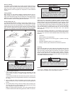
Starting, Stopping and Controlling Speed
1. To start the tool, grasp the handle firmly and pull the trigger.
2. To stop the tool, release the trigger. Allow the tool to come to a
complete stop before removing the blade from a partial cut or laying
the tool down.
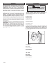
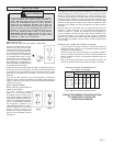
Selecting the Speed Range
The speed control dial controls the maximum strokes per minute. The
speed will remain variable to the chosen dial setting by use of the trigger
switch. Refer to the chart for recommended dial settings.
WARNING!
To reduce the risk of injury, wear safety goggles
or glasses with side shields. Unplug the tool
before changing accessories or making adjust-
ments.
Suggested dial settings*
2-3
5
5
1-3
4-5
1-3
1-3
2-3
2-3
Material
Mild Steel
Wood
Nail-Embedded Wood
Stainless Steel
Drywall
Fiberglass
Plastics
Cast Iron
Non-Ferrous
Metals
* These are only suggested settings; the actual optimum
setting may vary depending on line voltage, blade selected
and user preference.
Stroke
Fig. 5