


8 9
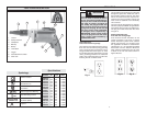
WARNING
To reduce the risk of injury, wear
safety goggles or glasses with
side shields. Unplug the tool
before changing accessories or
making adjustments.
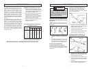
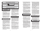
OPERATION
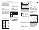
1. To increase the driving depth, simply
rotate the locator in the direction
labeled .
Fig. 8
1/16"
Locator
Deeper
Starting, Stopping and Controlling
Speed
1. To start the tool, pull the trigger.
2. To stop the tool, release the trigger.
3. To vary the drilling speed, simply in-
crease or decrease pressure on the
trigger. The further the trigger is pulled,
the greater the speed.
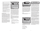
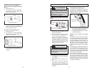
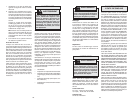
Locking Trigger (Fig. 7)
The lock button holds the trigger in the ON
position for continuous full speed use.
1. To lock the trigger, hold the lock button
in while pulling the trigger. Release the
trigger.
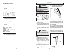
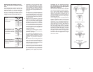
Using Forward/Reverse Switch (Fig. 6)
1. For forward (clockwise) rotation, push
the forward/reverse switch to the left
position as shown.
2. For reverse (counterclockwise) rotation,
push the forward/reverse switch to the
right position as shown.
Although an interlock prevents reversing
the tool while the motor is running, allow
it to come to a full stop before revers-
ing.
WARNING
To reduce the risk of injury, keep
hands and cord away from the bit
and all moving parts.
2. To unlock the trigger, pull the trigger and
release. The lock button will pop out.
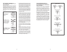
Adjusting Locator Assembly (Fig. 8)
The locator assembly controls the tool's
driving depth. These screwdrivers feature
a locator assembly with one-handed depth
adjustment. Depth adjustments can be made
easily and quickly by turning the locator with
one hand. Detents inside the sleeve “lock”
the selected depth.
For the drywall ramp-off locator assembly,
start with about 1/16" clearance between the
head of the screw and nose with the snap-
action clutch disengaged as shown.
For both locator assemblies, the detents on
the inside of the sleeve represent different
depths. Every two clicks of the locator equal
1/64". Continue adjusting the locator to the
desired depth.
Forward
Trigger
Fig. 6
Reverse
Switch
Lock
button
Fig. 7
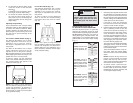
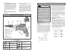
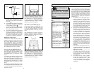
Installing and Removing Magnetic Sock-
ets on Adjustable Screwdrivers
For Cat. Nos. 6580-20 & 6581-20 (Fig. 4)
1. Unplug tool.
2. To remove the magnetic socket, slide
the locking sleeve forward and pull out
the socket.
Fig. 4
3. To install the magnetic socket, slide the
locking sleeve forward and push in the
socket until it is fully seated.
Fig. 5
For Cat. No. 6780-20 (Fig. 5)
1. Unplug tool.
2. To remove the magnetic socket, slide
the locking sleeve forward and pull out
the socket.
3. To install the magnetic socket, simply
push in the socket until it snaps into
place.
Locking sleeve
Socket
Locking sleeve
Socket