


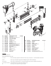

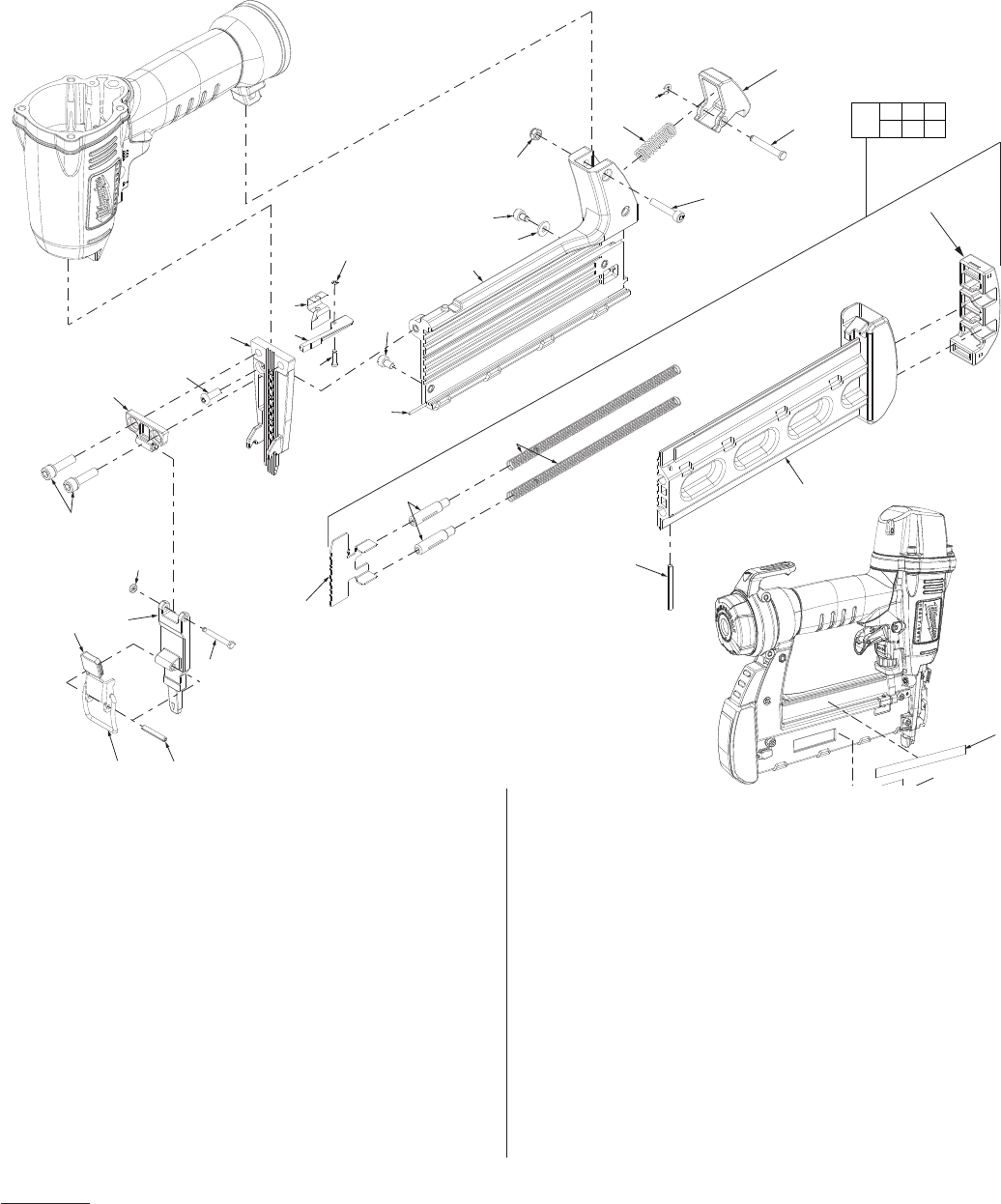
49 43-56-0861 Driver Guide 1
50 05-83-0505 Half Round Hex Bolt (M4 x 0.7-12) 1
51 42-92-1405 Cover, Driver Guide B 1
52 42-92-1390 Cover, Driver Guide A 1
53 44-60-1865 Fixed Pin 1
54 45-88-1705 Lock Handle Grip 1
55 06-65-1450 Spring Pin 1
56 44-20-0855 Lock Handle Assembly 1
57 43-40-0465 Magazine A 1
58 05-84-0880 Bolt, SHC, M4 x 0.7-6 1
59 42-36-2045 Work Contact Element Stop Bracket 1
60 40-50-3090 Work Contact Element Stop Pin 1
61 44-60-1880 Work Contact Element Stopper Pin 1
63 42-18-0300 Magazine Bar 1
64 40-50-3215 Magazine Latch Spring 1
65 44-20-0865 Latch 1
66 05-59-2040 Lock Nut, M4 x 0.7 1
67 43-72-0375 Pusher 1
68 45-08-0465 Pusher Spring Shaft 2
69 40-50-3125 Pusher Spring 2
70 43-40-0500 Magazine B 1
FIG. PART NO. DESCRIPTION OF PART NO. REQ.
71 06-65-1445 Spring Pin 1
72 44-50-0200 Latch Pin 1
73 44-90-0765 E-Ring 1
74 05-84-0890 Bolt M4 x 0.7-22 1
75 42-92-1470 Protecting Hood Cover 1
87 05-84-0840 Bolt Assembly 2
88 05-84-0810 Bolt M4 x 0.7-6 1
89 44-86-0700 Retainer 1
91 45-88-1730 Flat Washer 1
92 31-94-0105 Trigger Valve Assembly 1
93 45-24-0035 Magazine Assembly 1
99 12-98-0320 Service Nameplate 1
101 10-20-3310 Warning Label 1
14-70-0130 Overhaul Kit (Not Shown)
14-70-0195 Driver Maintenance Kit (Not Shown)
FIG. PART NO. DESCRIPTION OF PART NO. REQ.
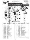
Lubrication:
Type I Grease 49-08-7100
Clean all parts with a dry, clean cloth.
2, 4, 5, 6, 7 Place a thin coating of grease into internal bore of top cap (2). Coat parts (4 – 7) and reassemble in order shown.
8, 9, 10 Coat o-ring (10) and piston ring (8) prior to installing into groove of driver assembly (9).
18, 20, 23, 24 Coat o-ring (13), cylinder spacer (15), o-ring (16) and cylinder ring (14) prior to installing onto cylinder (12).
21, 22 23, 24, 25, 26 27,
28
Coat individual parts of the trigger valve assembly (21-27).
Note: Plunger cover (28) does not require lubrication.
62
56
55
53
54
52
89
67
68
69
63
101
99
71
70
75
87
51
50
49
60
59
61
58
88
91
57
66
74
72
65
73
64
67 68 69
70 71 75
93