


98
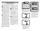
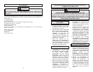
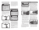
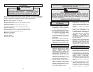
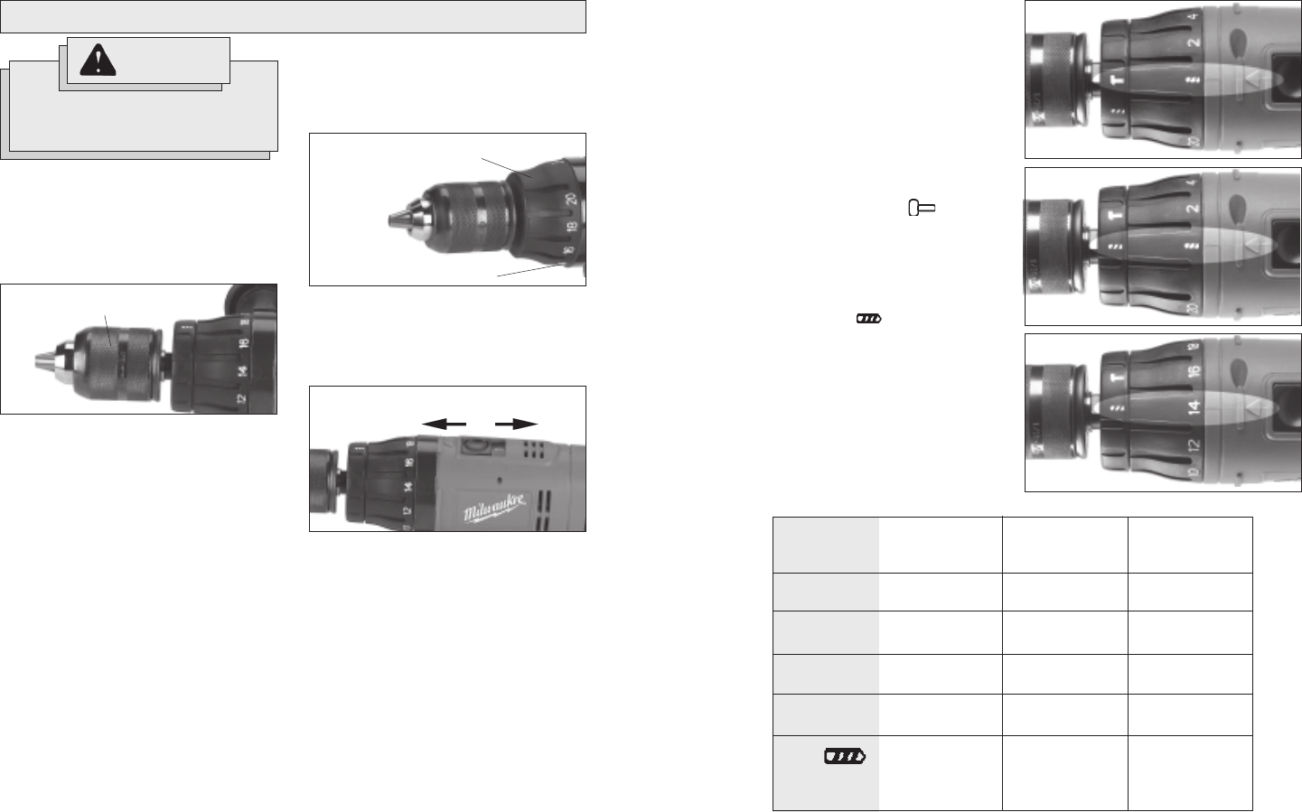
Selecting Hammer or Drill Action
(Cat. No. 0613-20, 0614-20, and 0624-20 only)
MILWAUKEE Hammer-Drills are designed
for two operating modes: drilling with ham-
mering action and drilling only. To set the
operating mode, rotate the hammer/drill se-
lector collar to the desired symbol. A drill or
hammer symbol will appear in line with the
arrow to indicate operating mode.
1. To use the hammer-drilling mode,
rotate the hammer/drill selector collar
until the hammer symbol appears
in line with the arrow. Apply pressure
to the bit to engage the hammering
mechanism.
2. To use the drilling only mode, ro-
tate the hammer/drill selector collar until
the drill symbol appears in line
with the arrow.
NOTE: When using carbide bits, do not use
water to settle dust. Do not attempt to drill
through steel reinforcing rods. Both ac-
tions will damage the carbide bits.
Fig. 6
To Hammer
Fig. 7
To Drill
Fig. 8
To Drive Screws
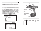
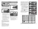
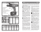
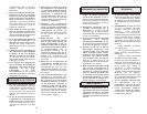
NOTE: Because the above settings are only a guide, use a piece of scrap material to test
the different clutch positions before driving screws into the workpiece.
Torque
selector
collar setting
1 - 5
6 - 10
11 - 15
16 - 20
Drill
Low
High
0 - 17 in. lbs.
21 - 38 in. lbs.
42 - 60 in. lbs.
65 - 85 in. lbs.
460 in. lbs.
160 in. lbs.
0614-20
& 0616-20
0 - 17 in. lbs.
21 - 38 in. lbs.
42 - 60 in. lbs.
65 - 85 in. lbs.
350 in. lbs
120 in. lbs.
Torque
0613-20
Torque
0 - 17 in. lbs.
21 - 38 in. lbs.
42 - 60 in. lbs.
65 - 85 in. lbs.
495 in. lbs.
175 in. lbs.
0622-20
& 0624-20
Torque
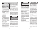
Selecting Speed (Fig. 5)
The speed selector is on top of the motor
housing. Allow the tool to come to a com-
plete stop before changing speeds. See
Applications for recommended speeds
under various conditions.
1. For Low speed (up to 500 RPM), push
the speed selector forward.
2. For High speed (up to 1700 RPM), push
the speed selector back.
OPERATION
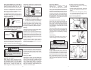
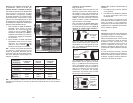
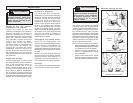
Using Keyless Chucks (Fig. 3)
Your cordless tool is equipped with a spindle
lock. The chuck can be tightened with one
hand, creating higher grip strengths on the bit.
Always remove the battery pack or lock
the trigger before inserting or removing bits.
1. To open the chuck jaws, turn the sleeve
in the counterclockwise direction.
When using drill bits, allow the bit to
strike the bottom of the chuck. Center
the bit in the chuck jaws and lift it about
1/16" off of the bottom.
When using screwdriver bits, insert
the bit far enough for the chuck jaws
to grip the hex of the bit.
2. To close the chuck jaws, turn the
sleeve in the clockwise direction. The
bit is secure when the chuck makes a
ratcheting sound and the sleeve can
not be rotated any further.
3. To remove the bit, turn the sleeve in
the counterclockwise direction.
NOTE: A ratcheting sound may be heard
when the chuck is opened or closed. This
noise is part of the locking feature, and
does not indicate a problem with the chuck's
operation.
WARNING!
To reduce the risk of injury, wear
safety goggles or glasses with
side shields.
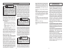
Using Clutch (Fig. 4)
This tool has an adjustable clutch for driv-
ing different types of screws into differ-
ent materials. When properly adjusted, the
clutch will slip at a preset torque to pre-
vent driving the screw too deep and to
prevent damage to the screw or tool.
Fig. 3
Sleeve
Fig. 4
Torque selector
collar
Position numbers
The torque specifications shown here are
approximate values obtained with a fully
charged battery pack.
To adjust the clutch, turn the torque selec-
tor collar to one of the twenty positions
shown on the collar. The number must line
up with the arrow on top of the tool.
Fig. 5
Low
High