


14
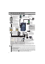
Wiring
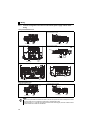
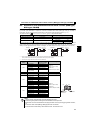
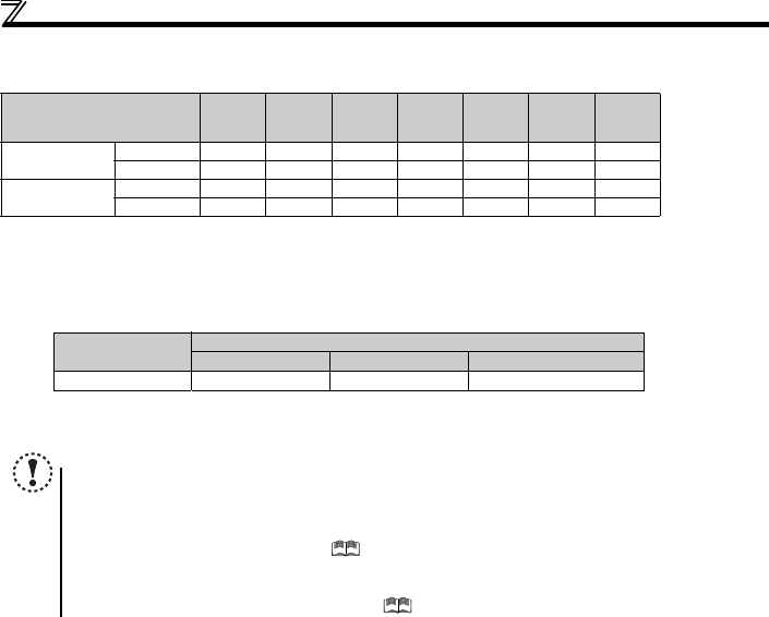
(2) Total wiring length
The overall wiring length for connection of a single motor or multiple motors should be within the value in the table below.
When driving a 400V class motor by the inverter, surge voltages attributable to the wiring constants may occur at the motor
terminals, deteriorating the insulation of the motor. Take the following measures 1) or 2) in this case.
1) Use a "400V class inverter-driven insulation-enhanced motor" and set frequency in Pr. 72 PWM frequency selection
according to wiring length.
2) Connect the surge voltage suppression filter (FR-ASF-H/FR-BMF-H) on the inverter output side.
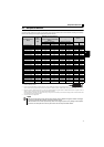
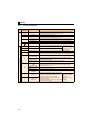
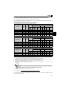
Pr. 72 PWM frequency selection
Setting
(carrier frequency)
0.1K 0.2K 0.4K 0.75K 1.5K 2.2K
3.7K
or More
1 (1kHz) or less
200V class 200m 200m 300m 500m 500m 500m 500m
400V class - - 200m 200m 300m 500m 500m
2 to15
(2kHz to 14.5kHz)
200V class 30m 100m 200m 300m 500m 500m 500m
400V class - - 30m 100m 200m 300m 500m
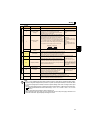
Wiring Length
50m or less 50m to 100m Exceeding 100m
Carrier frequency 14.5kHz or less 8kHz or less 2kHz or less
NOTE
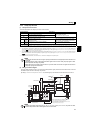
Especially for long-distance wiring, the inverter may be affected by a charging current caused by the stray
capacitances of the wiring, leading to a malfunction of the overcurrent protective function, fast response current limit
function, or stall prevention function or a malfunction or fault of the equipment connected on the inverter output side.
If malfunction of fast-response current limit function occurs, disable this function. If malfunction of stall prevention
function occurs, increase the stall level. ( Pr. 22 Stall prevention operation level and Pr. 156 Stall prevention operation
selection in Chapter 4 of the Instruction Manual (Applied))
When using the automatic restart after instantaneous power failure function with the wiring length exceeding 100m,
select without frequency search (Pr. 162 = "1, 11"). (
Refer to Chapter 4 of the Instruction Manual (Applied))