


5
Wiring
Tools and Materials
Pencil
Drill
Drill bit: 3mm or 1/8"
Cutting pliers
Phillips screwdriver
Wire strippers
Electrical tape
Blade screwdrivers
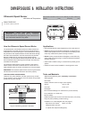
Locating the Junction Box and Cable Routing
Caution: Minimize electrical interference by separating the sensor
cables from other electrical wiring and the engine.
Caution: Be careful not to tear the cable jackets when passing
them through the bulkhead(s) and other parts of the boat.
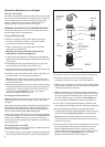
1. Select a convenient, dry, mounting location for the waterproof
junction box, about 1–2m (3' – 5') from the instrument (see
Figure 6).
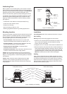
2. Route the sensor cable to the proposed location of the junction
box. Do not fasten the cable in place at this time.
3. Hold the junction box at the selected location and mark the
position of the four screw holes with a pencil.
Note: If the junction box will be mounted on a vertical surface, face
the compression bushings downward to avoid water seeping into
the box.
4. At the marked locations, drill a 3mm or 1/8" hole to a depth of
10mm (3/8"). Do not screw the junction box in place at this time.
5. Route the instrument cable to the junction box. Cut the cable
50cm (2') beyond the junction box to allow for wiring ease.
Do not fasten the cable in place at this time.
6. Route the power cable from the battery to the junction box.
Allowing 25cm (10") at each end for wiring ease, cut the cable
to length. Do not fasten the cable in place at this time.
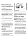
Preparing the Cables
WARNING: The power must be “off” before proceeding.
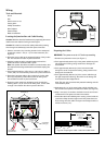
1. Remove the junction box cover (see Figure 7).
2. Push approximately 200mm (8") of the power cable through the
left compression bushing, being careful not to damage the
circuit board.
3. Push approximately 200mm (8") of the instrument cable
through the center compression bushing, being careful not to
damage the circuit board.
4. Push approximately 200mm (8") of the sensor cable through
the right compression bushing. Be careful not to damage the
circuit board and the stripped wires.
Note: The grey wire is covered with protective sleeving and this
must remain in place.
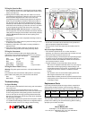
5. Strip 60mm (2-1/2") of the outer jacket and foil shielding from
the cut ends of the power and instrument cables (see Figure 8).
6. Strip 11mm (3/8") of conductor insulation from the end of each
insulated wire in the power and instrument cables.
7. Protect the cable’s foil shielding from causing a short inside the
junction box. Wrap electrical tape around the jacket where the
wires emerge from the cable. The tape must overlap the wires a
minimum of 6mm (1/4").
Figure 6. Cable layout
compression
Figure 7. Junction box
screw hole (4)
60mm (2 1/2")
remove outer jacket
11mm
(3/8")
cable
jacket
remove
insulation
Figure 8. Preparing the cable—instrument cable shown
electrical
tape
BRN
WHT
GRN
BLK
RED
RED
GRN
BARE
WHT
BRN
RED
BLK
BATTER
Y
INSTRUMENT
SENSOR
bushing (3)
sensor
instrument
power panel
(battery)
grey
wire with
protective
sleeving
SERVER
RED
From Server
From Sensor
From Battery
Log input
Use 2A Fuse