


6
BRN
WHT
GRN
BLK
RED
RED
GRN
BARE
WHT
BRN
RED
BLK
BATTER
Y
INSTRUMENT
SENSOR
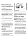
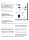
Wiring the Junction Box
1. From outside the junction box, carefully pull each of the cables
in turn until only 13mm (1/2") of the cable jacket remains inside
the box (see Figure 9).
2. Starting with the battery cable, wire each cable in turn to the
corresponding terminal block. Follow the color code on the PC
board. Insert the stripped end of a wire in the hole in the
corresponding terminal. Simultaneously depress the adjacent
button using a small blade screwdriver. Release the button to
lock the wire in place. Be sure the stripped end of the wire is
inserted up to the insulation only
. Do not include any insulation
inside the terminal. Gently tug on the wire to ensure it is locked
in place. Repeat this process until all wires are connected.
Caution: Sensor cable
—Do not attempt to connect the bare
wire and grey wire. The bare wire has been cut off flush with the
cable jacket, and the grey wire has been covered with protective
sleeving. Do not allow these wires to short anything in the
junction box.
3. Hand-tighten the nut on each compression bushing to make a
waterproof seal.
4. Arrange the wires neatly inside the junction box being sure that
no bare wires are touching.
5. Attach the junction box cover with the screws provided for a
waterproof seal.
6. Using the screws provided, attach the junction box to the
selected mounting surface at the holes previously drilled.
Wiring the Instrument
To connect the instrument cable to the display, follow the
instructions in your instrument owner’s manual for connecting a
speed sensor. See the color code below.
Red B+ (5 to 15V)
Green (GRN) signal
Bare ground
White (WHT) temperature
Brown (BRN) temperature
Wiring the Power Panel (Battery)
Warning: The power panel must have a 1/2 amp fast blow fuse or
breaker.
Cut off the bare wire flush with the cable jacket. To connect the
power cable to the power panel, see the color code below.
Red
+
10 to 15 VDC
Black (BLK)
–
VDC
Troubleshooting
No Speed Reading
• Is the ultrasonic insert installed in the housing and connected to
the junction box?
• Is the ultrasonic insert oriented with the arrow on the top
pointing forward toward the bow? If the insert cannot be seated
in the housing with the arrow pointing forward, check that the
arrow on the lip of the housing is pointing forward toward the
bow. If this is not the case, the housing needs to be reinstalled
with the proper orientation.
• Is power being supplied to the junction box? The power must be
10-15VDC. At lower voltages performance is degraded and the
unit will shut down. If there is no voltage, check the wiring.
• Are the wire connections at the terminals in the junction box
tight and properly stripped of insulation?
• Does the color of each wire match the color label on the PC
board?
Inaccurate Speed Readings
• If the ultrasonic speed sensor is “on” when the boat is
stationary, you may see a speed readout of a fraction of a knot
because of water movement under the hull.
• If the speed reading is consistently the same percentage higher
or lower than the true speed, the speed function within the
instrument needs to be recalibrated. Follow the instructions in
your instrument owner’s manual.
• If speed readings are inaccurate above about 10knots:
- The sensor is installed in turbulent water. The cause may be
water intake or discharge openings, strakes, fittings, hull
irregularities upstream of the sensor, or the shape of the hull
in that area. The sensor must be re-installed in another
location.
- The ultrasonic insert is covered with aquatic growth. See
“Servicing the Ultrasonic Insert” on page 4.
- Aerated water is flowing across the sensor because the boat
is designed to pull air under the hull. The sensor will not work
on this type of boat.
Replacement Parts
If you have purchased a plastic housing and have a wood hull or
desire greater strength, purchase a bronze housing. Obtain the
following parts from your marine dealer or instrument manufacturer.
Sensor Replacement
The information needed to order a replacement Airmar sensor is
printed on the cable tag. Do not remove this tag. When ordering,
specify the part number and date.
Blanking
Plug
Cap Nut Hull Nut
Housing, Washer
& Hull Nut
O-ring &
Valve Kit
20-600
04-234-1 (plastic)
02-131-01 (bronze)
04-004 (plastic)
02-030 (bronze)
33-340-02 (plastic)
33-340-01 (bronze)
33-450-01
AIRMAR
TECHNOLOGY CORPORATION
35 Meadowbrook Drive, Milford, New Hampshire 03055-4613, USA
www.airmar.com
Figure 9. Wiring the Junction Box
button
button
Copyright ©:
Nexus Marine AB
Kuskvägen 4, 191 62 Sollentuna, Sweden
Tel: +46 -(0) 8 – 506 939 00. Fax: +46 -(0) 8 -506 939 01
www.nexusmarine.se
Nexus Server
Green
Yellow
Bare
Wite
Jumper from Bare