


www.norcold.com/cda 21N6XX/N8XX ModelsRefrigerator Service Manual
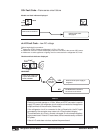
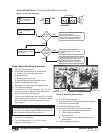
n/no co Fault Code – No cooling detected by the controls
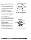
Power Board Resetting Procedure
1. Turn OFF the refrigerator.
2. Disconnect the following from power board:
a. 12 Vdc positive and negative wires.
b. AC power cord.
c. Solenoid gas valve wires.
d. Spark/sense electrode assembly wires.
3. Remove the power board cover.
4. Reconnect 12 Vdc positive and negative wire.
5. Turn ON the refrigerator.
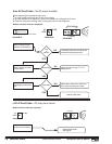
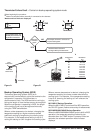
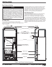
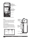
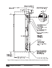
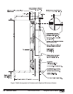
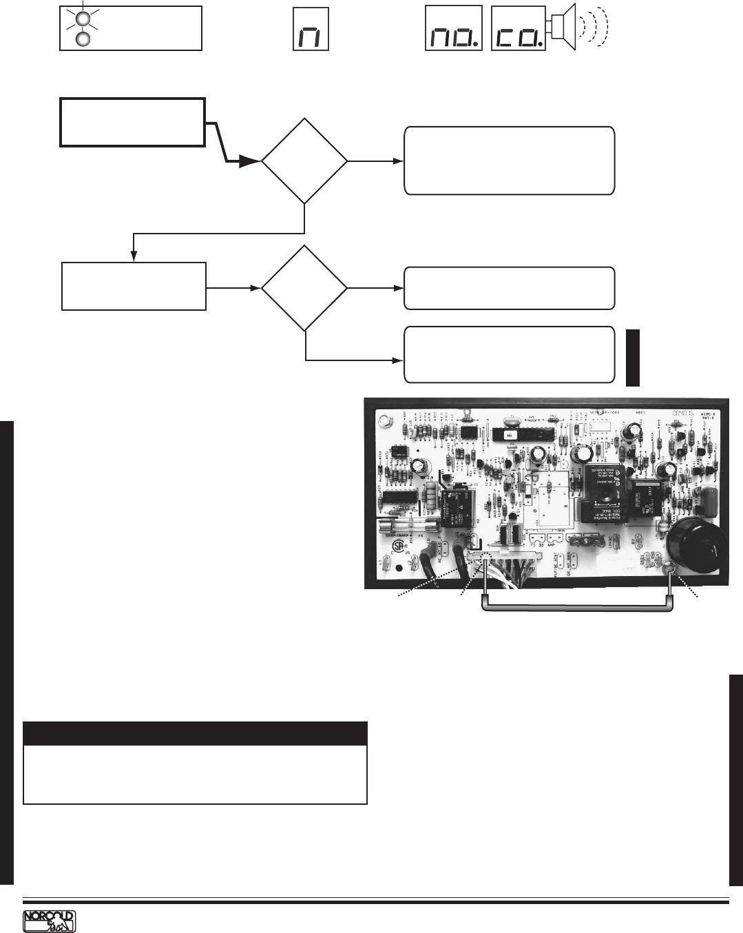
6. Locate Pin 15 on 16 pin connector (P1). Pin 15 is
the empty socket to the right of the white/violet
wire on the top row. See Figure C.
7. Using an insulated jumper wire, short Pin 15 to the
power board ground lug for 10 - 15 seconds. A click
sound will indicate when the controls are reset.
See Figure C.
10. Turn OFF the refrigerator.
11. Disconnect the 12 Vdc power positive and negative
wires from the power board.
12. Install the power board cover.
13. Reconnect the following to the power board:
a. Spark/sense electrode assembly wire.
b. Solenoid gas valve wires.
c. AC power cord.
d. 12 Vdc positive and negative wires from the
power board.
14. Place refrigerator in service.
8. Turn OFF the refrigerator.
9. Turn ON refrigerator. If "n" or "no co" code
displays, repeat steps 7 - 9.
NOTE
A jumper wire to short Pin 15 to ground can be made
from a six inch long insulated 22 AWG wire with a 1/2
inch of insulation stripped from each end.
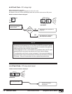
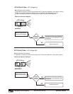
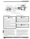
N62X/N82X
LP GASAC
AUTO
ON
GAS
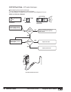
ON LED flashing
5 times e
very
3 seconds
Models and indicator displayed.
NO
YES
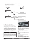
Check for completion of
cooling cycle after resetting
power board.
NO
Cooling unit is good. Recheck for
ventilation obstructions and leveled
operation.
YES
Check for cooling at fin
assembly.
"no" "co"
code shows
before cycle
end?
Cooling
detected?
1. Check for ventilation obstructions
and leveled operation.
2. Reset power board as shown in
figure and described in procedure.
3. Allow unit to operate normally.
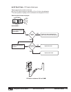
1.
Replace cooling unit if "no" "co" shows
before completing a full cooling cycle.
2. Reset power board as shown in
figure and described in procedure.
D
i
s
p
l
a
y
A
l
t
e
r
n
a
t
i
n
g
N64X/N84X
Audible
Alarm
N61X/N81X
Pin 16
White/violet wire
To pin 15
Ground Lug
Insulated wire jumper
22 AWG with 1/2" long stripped ends
Figure C. Resetting Power Board.
Errata Sheet, 01/16/04