


www.norcold.com/cda 35N6XX/N8XX ModelsRefrigerator Service Manual
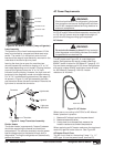
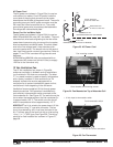
AC Power Cord
The AC power cord shown in Figure 23(a) is used on
units without ice maker. On all AC power cords the
round side of the plug that connects to the power
board faces the left side of the power board. The cord's
grounding prong on the AC outlet connector must be
left intact and never be modified or cut. The cord's
ground wire (green wire) must always be fastened to
the refrigerator cabinet metal plate.
Power Cord for Ice Maker Units
The AC power cord shown in Figure 23(b) is used on
N64X IM and N84X IM units (IM = ice maker). The cord
has two short wire leads originating at the rear of the
power board connector plug to connect the ice maker
wire harness black and white leads. The short ribbed
wire is the line voltage lead, it has a female quick-
connect type terminal. The smooth wire is the neutral
lead, has a male quick-connect type terminal. Refer to
pages 71 and 72 for ice maker wiring pictorials and
diagrams.
All N643IM and N843IM units are equipped with an
independent AC power cord (white in color) to supply
120 Vac to the ice maker only.
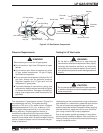
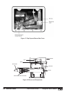
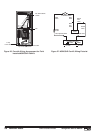
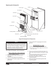
12 Vdc Ventilation Fan
The 12 Vdc ventilation fan, shown in Figure 24,
enhances ventilation in sidewall venting installations
(unit installed in RV slide out enclosures). The letter
"F" in a model number is used to identify refrigerators
with a factory installed 12 Vdc ventilation fan. All
sidewall vented units must be equipped with a
ventilation fan to prevent combustion gases and hot
ventilation air from stagnating in the enclosure.
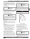
Ventilation fans are supplied 12 Vdc through power
board connections. Fan operation is automatically
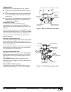
controlled by a thermostatic switch mounted on the
first condenser fin. See Figure 25. The switch turns the
fan on when the temperature on the first condenser fin
is approximately 130 °F. The switch turns the fan off
when fin temperature falls to approximately 115 °F.
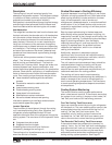
NORCOLD
®
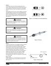
fan kit is wired to the power board 12 Vdc
connections using "Y" type wire connector. The fan
circuit is protected by an in-line fuse (included in the
kit). The fuse, part of the fan kit wiring is a fast acting
1 amp,
1
/
4
” x 1
1
/
4
” AGC type. See Figure 26. The wiring
pictorial for field installed fan is shown in Figure 27,
page 36.
Figure 24. Fan Mounted on Top of Absorber Coil.
Figure 25. Fan Thermostat.
Figure 23. AC Power Cord.
Ground wire
Ribbed black lead
to white ice maker wire
Smooth black lead
to black ice maker wire
Ground wire
REFRIGERATORS WITH ICE MAKERS
REFRIGERATORS WITHOUT ICE MAKERS
(a)
(b)
Outer bracket and mounting screws
Fan mounting screws
+12 Vdc wire to fan connection
Fan thermostatic switch
+ 12 Vdc input to thermostatic switch