


www.norcold.com/cda
68
Refrigerator Service ManualN6XX/N8XX Models
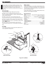
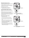
Cycle Test
Cycle testing the ice maker will confirm if the mold
heater energizes and motor complete a full cycle.
However, if the ejector fingers are trapped in the ice
allow the ice to partially thaw before cycle testing the
ice maker.
To cycle test the ice maker:
1. Shut off the water supply to the ice maker water valve.
2. Remove the ice maker cover.
3. Place the shut-off arm in the ON position (down).
4. Make sure 120 VAC is available to the ice maker.
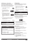
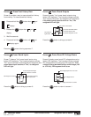
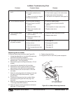
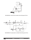
5. Measure voltage across test points L and N. See Figure
51. Voltage reading should be between 108 to 120 Vac. If
no voltage present, check the continuity of the ice maker
wire harness.
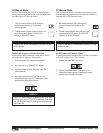
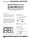
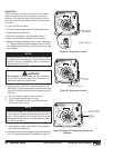
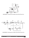
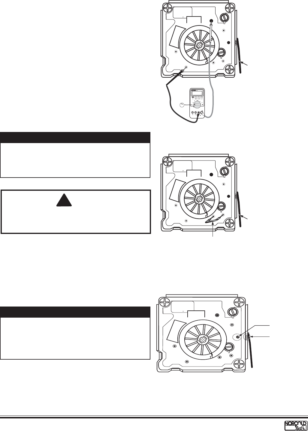
Figure 52. Test points T and H.
6. Short terminals T and H. An insulated jumper wire 14
AWG with 1/2 inch stripped ends is recommended. See
Figure 52. The following events should take place during
the cycle:
a. The mold heater begins to heat the mold.
b. The ice maker ejector starts to cycle.
c. About 15 seconds into the cycle, the thermostat
produces a “click” sound.
Figure 51. Test points L and N.
108 to 120 Vac
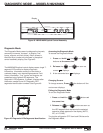
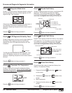
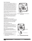
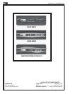
Figure 53. Water Fill Adjustment Screw and
Indicator.
Shorting test points T and H will start the cycle. Remove
the jumper wire from test points T and H when a click
sound is heard or immediately after 15 seconds of
shorting terminals T and H.
NOTE
Remove the jumper wire immediately after hearing the
"click" sound or 15 seconds after shorting terminals T
and H. Failing remove to the jumper wire will cause
damage to the heater and/or overheat the mold, which
will ruin the ice maker.
NOTE
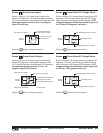
d. As the ejector fingers reach the 12 o'clock position
the water valve energizes.
6. If the water valve does not remain energized between 3.5
and 7.5 seconds, see Water Fill Adjustment, page 70.
!
WARNING:
Burn hazard! The mold heater will heat the bottom
of the mold. Handle or grasp the ice maker by its
sides when performing a cycle test.
D
O
N
O
T
R
O
T
A
T
E
M
A
N
U
A
L
L
Y
V
L
T
H
M
N
DISCONNECT POWER
TO REMOVE MODULE
U
R
185W-115V-60 HZ
IM # S 106 626649
11 MAY 00
WB1
Shut-Off Arm
(ON position)
MIN MAX RANGE HOLD
H
HzREL
mA
A
mV
V
V
OFF
!
!
A
COM
V
mA µA
1000V MAX
400mA MAX
FUSED
10A MAX
FUSED
PEAK MIN MAX
µA
CAT II
4 1/2 DIGITS
1 Seconds
87
TRUE RMS MULTIMETER
III
V
V
D
O
N
O
T
R
O
T
A
T
E
M
A
N
U
A
L
L
Y
V
L
T
H
M
N
DISCONNECT POWER
TO REMOVE MODULE
U
R
185W-115V-60 HZ
IM # S 106 626649
11 MAY 00
WB1
Insulated Jumper Wire
(14 AWG with 1/2" stripped ends)
Shut-Off Arm
(ON position)
D
O
N
O
T
R
O
T
A
T
E
M
A
N
U
A
L
L
Y
V
L
T
H
M
N
DISCONNECT POWER
TO REMOVE MODULE
U
R
185W-115V-60 HZ
IM # S 106 626649
11 MAY 00
WB1
Water fill adjustment
alignment indicator
Water fill
adjustment
screw