


OPERATION
BEFORE OPERATING YOUR NEW AIR
COMPRESSOR please check the following points
carefully:
1 Check that all nuts and bolts are secure.
2. Make sure oil has been properly added to
compressor. (See Installing Oil and Oil Breather
Cap section.)
Initial Start-Up Procedure
1. Open the Air Tank Drain Valve to permit air to
escape, preventing air pressure buildup in the
air tank.
2. Run the compressor for a minimum of 20
minutes in this “no-load” position to lubricate the
piston and bearings.
3.
Close Air Tank Drain Valve. Your compressor is
ready for use.
Depending on the CFM draw of the tools being
operated, your new Air Compressor can be used for
operating paint sprayers, air tools, grease guns,
airbrushes, caulking guns, abrasive blasters, tire &
plastic toy inflation, spraying weed killer and
insecticides, etc. Proper adjustment of the Air
Pressure Regulator is necessary for all of these
operations. Refer to the air pressure specifications
provided with the tool you are using.
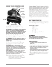
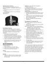
General Overview
To compress air, the piston moves up and down in
the cylinder. On the down stroke air is drawn in
through the valve inlet. The discharge valve remains
closed. On the upstroke of the piston air is
compressed. The inlet valve closes and air is forced
out through the discharge valve, through the check
valve, and into the air tank. W
orking air is not
available until the compressor has raised the tank
pressure above that required at the air service
connection. The air inlet filter openings must be
kept clear of obstructions, which could reduce air
delivery of the compressor.
Installation and Location
Locate the compressor in a clean, dry and well
ventilated area. The compressor should be located
12 to 18 inches from walls or any other obstruction
which would interfere with airflow. Compressor
should be loacted in a temperature controlled area
between 32º and 95º fahrenhert. Place the
compressor on a firm, level surface. The
compressor is designed with heat dissipation fins
which allow for proper cooling. Keep the fins (and
all other parts which collect dust or dirt) clean. A
clean compressor runs cooler and provides longer
service. Do not place rags, containers or other
material on top of the compressor.
Connecting to Power Source
This air compressor is designed to operate on a
properly grounded 120 volt, 60Hz, single phase,
alternating current (ac) power source with a fused
20 amp time delayed fuse or circuit breaker. It is
recommended that a qualified electrician verify the
ACTUAL VOLTAGE at the receptacle into which the
unit will be plugged and confirm that the receptacle
is properly fused and grounded. The use of the
proper circuit size can eliminate nuisance circuit
breaker tripping while operating your air
compressor.
Extension Cords
For optimum Air Compressor performance an
extension cord should not be used unless
absolutely necessary
. If necessary, care must be
taken in selecting an extension cord appropriate for
use with your specific Air Compressor. Select a
properly grounded extension cord which will mate
directly with the power source receptacle and the
Air Compressor power cord without the use of
adapters. Make certain that the extension cord is
properly wired and in good electrical condition.
Maximum length of extension cord should be 50
feet. Minimum wire size of extension cord should be
12 gauge.
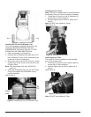
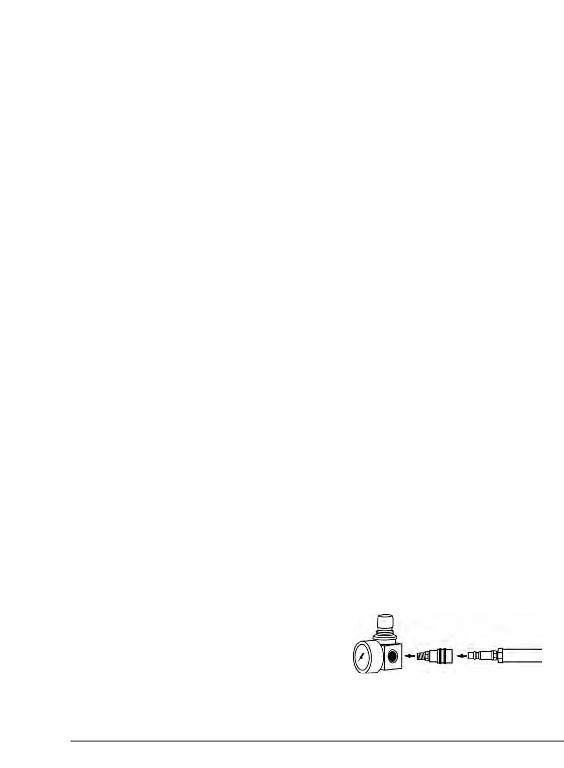
Attaching an Air Hose
Your Air Compressor is supplied with a 1/4" Quick
Disconnect Air Chuck. Once you have correctly
installed the Air Chuck (See Installing the Air Chuck
on p.4) your compressor will be ready to accept air
hoses equipped with 1/4" male air couplers.
Note: Use only air hoses rated for use with 115psi
air pressure or higher.
To install an air hose, equipped with a 1/4" male
coupler:
1. Pull back on Air Chuck outer sleeve to allow
coupler to be fully inserted into Air Chuck.
2.
Insert coupler into
Air Chuck.
3. Release outer sleeve of Air Chuck.
4.
Verify that air hose is securely connected to Air
Chuck by pulling lightly on air hose.
(See Figure 6)
Figure 6. Attaching an
Air Hose
5