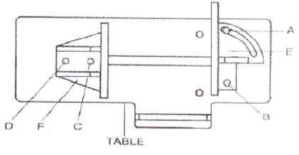
QUICK VISE ADJUSTMENT FOR ANGLE CUT
ust rear vise to the threaded hole position.
e rear vise
. Tighten the A, B, C and D screws.
will not cut straight, and if the situation is not corrected
If a new blade does not correct the problem, check
ance between the blade and guide
nd can be adjusted.
tric bushing by turning the bolt to the desired position of clearance.
. Tighten the nut.
BLADE TRACK ADJUSTMENT
er tighten the saw blade
e to cause the basic setting to be misaligned. Should this occur,
pr
ain in the threaded hole.
1. Loosen the A, B, C and D screws.
2. Adj
(E)
3. Set the scale to the desired angle.
4. Adjust the front vise (F) to parallel th
(E).
5
BLADE GUIDE BEARING ADJUSTMENT
ATTENTION: This is the most important adjustment on your saw. It is impossible to get satisfactory
work from your saw if the blade guides are not properly adjusted. The blade guide bearings on your
Metal-Cutting Band Saw are adjusted and power-tested with several test cuts before leaving the
factory to insure proper setting. The need for adjustment should rarely occur when the saw is used
properly. If the guides do get out of adjustment, it is extremely important to readjust immediately. If
improper adjustment is maintained, the blade
it will cause serious blade damage.
Because guide adjustment is a critical factor in the performance of you saw, it is always best to try a
new blade to see if this corrects poor cutting before beginning to adjust. If a blade becomes dull on
one side sooner than the other, for example, it will begin cutting crooked. A blade change will correct
this problem while the guide adjustment will not.
the blade guides for proper spacing.
NOTE: There should be from 000 (just touching) to 001 clear
bearings. To obtain this clearance adjust as follows:
1. The inner guide bearing is fixed and cannot be adjusted.
2. The outer guide bearing is mounted to an eccentric bushing a
3. Loosen the nut while holding the bolt with an Allen wrench.
4. Position the eccen
5
1. Open the blade guard.
2. Remove the blade guide assemblies (top and bottom).
3. Loosen the hex head screw in the tilting mechanism to a point where it is loose but still snug.
4. With the machine running, adjust both the set screw and blade tension knob simultaneously to
keep constant tension on the blade. The set screw and blade tension knob are always turned in
opposite directions, i.e., when one is turned clockwise, the other is turned counterclockwise. The
blade is tracking properly when the backside just touches the shoulder of pulley or a slight gap
appears near the center line of the pulley. Care should be taken not to ov
since this will give a false adjustment and limit life of the blade.
5. Tighten the hex head screw in tilting mechanism. IMPORTANT: Sometimes in trying to make this
critical adjustment, it is possibl
oceed as follows:
a. Loosen the set screw and back it out as far as it can go and still rem
Page 8 of 15


