


49
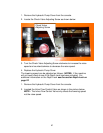
2. Use a circuit "test light" to test switch. (See Test Equipment
Section)
3. Remove the wires from the switch and "touch" them
together in the proper order to operate system.
NOTE: All switch control stations subjected to the weather
should be mounted so that the cord exits the bottom to
prevent water from entering the box.
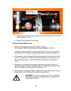
G. Motor Start Solenoid Switches
The three post solenoid switch is wired and constructed as
follows:
1. The large post marked "Bat' must be attached to he cable
leading from the battery.
2. The small post connects to the control circuit. (Contact
finger, push button, toggle switch, etc.) The remaining
large post attaches to cable leading from motor.
NOTE: Do not attach motor cable to post marked "Bat" as
solenoid will not operate properly.
4. Internally, the coil is constructed with one end connected to
the post marked "Bat" and the other end to the small center
post. With the battery cable connected to the post marked
"Bat," the solenoid switch is energized by grounding the
small post: which in turn closes the main contacts and starts
the motor.
NOTE: When testing, use an OHM meter, continuity light or
test light, and check all functions as described above. (See
Test Equipment Section)
H. Shorts, "Ground Faults" and "Open" Circuits
In control wiring, shorts can only occur when "hot" lines (lines
connected directly to the battery) come in contact with
ground. A short will either cause a fuse to blow, if there is
one, or bum the wire off at its weakest point. Likely spots for
shorts are switches, electrical strain relief, electrical junction
boxes and control cord that has been pinched or cut.
Grounding faults are much like shorts except they occur on
the opposite side of the electrical component. (Valve solenoid
or motor solenoid start switch.) A "ground fault" will cause the
coil in the motor solenoid switch or valve to remain energized.
This type of failure can happen because switching is done in