


page 3
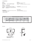
OMEGA FP-5060 Series Micro Flow Sensor
Technical Notes:
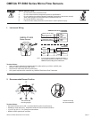
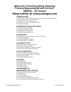
• Horizontal surface mount (±30 °) recommended for optimum performance.
• Suitable for clean fl uids only. Suspended solids will cause mechanical failure.
• ¼ in. NPT or ISO 7/1 - R¼ (male) port connections
• NEMA 4X/IP65 splashproof enclosure
0°
30°30°
Recommended
mounting angles
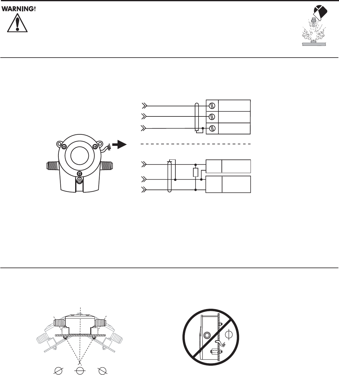
Vertical mounting
not recommended
OMEGA FP-5060 Series Micro-Flow Sensors
2. Recommended Sensor Position
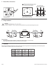
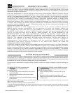
1. Instrument Wiring
Technical Notes:
• Use 2-conductor twisted-pair shielded cable for cable splices up to 300 m (1000 ft) max.
• Maintain cable shield through cable splice.
• Route sensor cable away from AC power lines.
• AUX power required when used with any OMEGA FP90 Series Flow Transmitter.
OMEGA FP-5060
Series Sensor
Input
Gnd.
10 kΩ
+
5 to 24
VDC
-
Black
Shield
Red
Other
instrument
Black (5 to 24 VDC)
Red (Signal out)
Shield (DC return)
Blk
Power
Red
Freq. input
Shld
Gnd
Other
Instrument
OMEGA FP-90 Series, FPM-5500,
FPM-9020A
Note: A 10 kΩ pull-up resistor is required as shown, if
not provided internal to the instrument. Contact
OMEGA Technical Support for assistance.
SAFETY INSTRUCTIONS
1. Do not remove from pressurized lines.
2. Do not exceed maximum temperature/pressure specifi cations.
3. Do not install/service without following installation instructions (see sensor manual).
4. Wear safety goggles and faceshield during installation/service.
5. Do not alter product construction.
6. Failure to follow safety instructions could result in severe personal injury!