


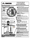
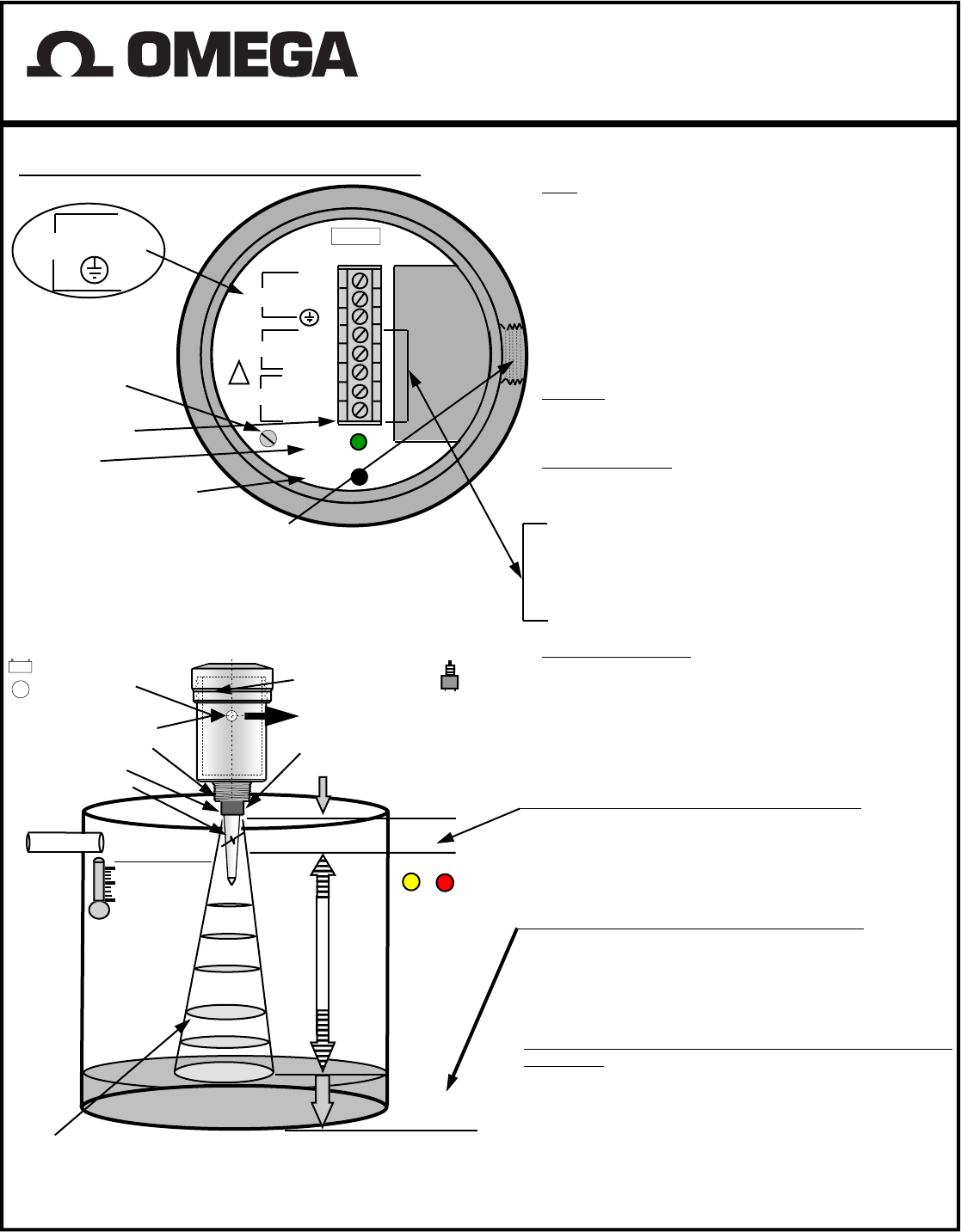
Inter-Connection Diagram
Top View of Sensor (Access Cover Removed)
FCC INFORMATION TO RADAR USERS
NOTE: This equipment has been tested and found to comply
with the limits for a Class A digital device, pursuant to Part
15 of the FCC Rules. These limits are designed to provided
reasonable protection against harmful interference when
the equipment is operated in a commercial environment.
This equipment generates, uses, and can radiate radio fre-
quency energy and, if not installed and used in accordance
with the instruction manual, may cause harmful interfer-
ence to radio communications. Operation of this equipment
in a residential area is likely to cause harmful interference
in which case the user will be required to correct the inter-
ference at his own expense.
WARNING-Changes or Modifications not expressly approved
by the Manufacturer could void the user’s
authority to operate the equipment.
Wiring Information
- Ground shield at one end only.
- All terminal block wiring must be rated for 250V.
- Power input wiring must be protected by a 15A double
pole circuit breaker .
- Terminal is for use only with equipment which has no live
parts which are accessible .
- Terminal is for use with equipment which maintains basic
insulation from hazardous voltage under normal and sin-
gle fault conditions .
- Connection used at the remote end of external circuit .
Recommended Wiring
For AC Sensor —
Power 3 Wire unshielded 22 AWG , 300 V
Current Output 1 Pair shielded 24 AWG , 300 V
Communication 1 Pair shielded 24 AWG , 300 V
For DC Sensor—
Power & Current output 3 Wire shielded 24 AWG , 300 V
Status LED
Terminal Block
+ 8
12– 30 VDC -- 7
6
DC Power Input
Note - TB #7 is
Connected to TB #4
RS232/485
L1 8
4-20 mA
AC IN
SHIELD 3
STATUS
A/TX 2
B/RX 1
— 4
+ 5
L2/N 7
6
SWITCH
- F1/8 A 250V
CALIBRATION
FUSE
Control Panel
Fastening Screw
!
Calibration Pushbutton
NOTE — Use only 1/2” NPT Conduit
Calibration — 4 -20 or 20 - 4 mA Output
FULL — Calibrate 20 mA or 4mA (Set Near Target)
1. Calibration mode LED color is Green.
(for Radar Low Dielectric Materials has to be off)
2. Push button and hold until LED turns Yellow (20 mA)
or push button and hold until LED turns Red (4 mA)
3. Release button, observe LED flashes to acknowledge
the calibration.
EMPTY— Calibrate 4 mA or 20 mA (Set Far Target)
1. Calibration mode LED color is Green
(for Radar Low Dielectric Materials has to be off)
2. Push button and hold until LED turns Red (4 mA)
or push button and hold until LED turns Yellow (20 mA)
3. Release button, observe LED flashes to acknowledge
the calibration.
For Radar to turn the Low Dielectric Materials operation mode
ON and OFF
(this mode is recommended for materials with
dielectric constant lower than 4.)
1) To turn the Low Dielectric Materials ON. Push button and
hold until LED goes OFF after the sequence of Yellow , Red and
turns Off. The Low Dielectric Material operation is On when the
LED’S Green light blinks constantly.
2) To turn the Low Dielectric Materials OFF. Push button and
hold until LED goes OFF after the sequence of Yellow , Red and
Turns OFF. The Low Dielectric Material operation is OFF when
LED is continuously Green.
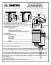
Operation - An ultrasonic/electromagnetic pulse is transmitted from the
sensor . The pulse travels to the surface being monitored and is re-
flected off this surface back to the sensor . The time of flight is divided
by 2 and converted to an output signal directly proportional to the
material level .
A
C
C
U
R
A
C
Y
R
E
S
O
L
U
T
I
O
N
Per
Chart
CALIBRATION PUSHBUTTON
/ Led Indicator For 4 - 20 mA
(750 ohm Max.) output
Deadzone
+/—0.25%
EMPTY
4 or 20mA
20 or 4 mA
FULL
Level
Material
S
P
A
N
LED
Red
Yellow
12 - 30 Vdc
115 / 230 Vac
60 / 50 Hz
˜
1/2” NPT Conduit Hole
1”, 1 1/2”, 2” , 3”NPT
Ultrasonic Sensor
Radar Rod Antenna
OPTIONAL Programmable
Calibration & Diagnostics, Data
Logging, RS232 or RS485 Com.
Temperature Compensation for the
speed of sound .
Process Temperature
Radar ;190° F/90°C
— 40° F/°C
Ultrasonic ;
140° F/60 °C
— 40° F/° C
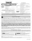
Typical Installation
1) DIRECT MOUNTING ULTRASONIC SENSOR -SIMPLY THREAD SENSOR
DIRECTLY INTO METAL OR PLASTIC NOZZLE.
2) RADAR UNIT MUST BE INSTALLED INTO METAL FITTING WITH THE ANTENNA
POINTING DOWNWARD.
Instruction Manual
For LVU and LVRD Series
Ultrasonic and Radar Sensors