


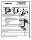
FUSE
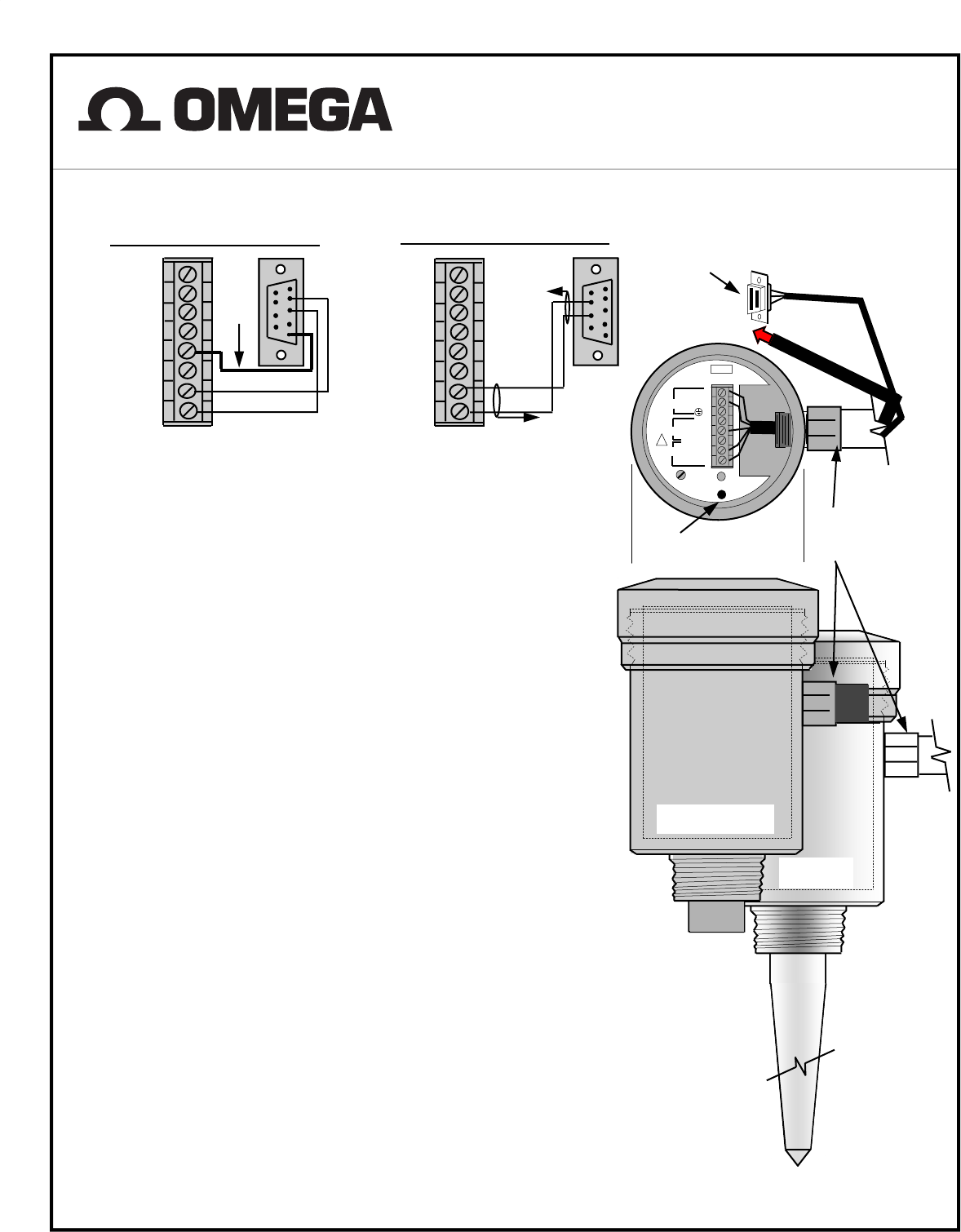
Connect to Serial Port of PC ,use
Extension Cable length as required
,Refer to Fig.# 1 or # 2 For Wiring
Fig. # 2 RS485 Connection
Sensor Terminal
DB9
1
2
3
4
5
6
7
8
9
Red
DB9
Sensor Terminal
Fig. # 1 RS232 Connection
L1 8
L2/N 7
GND. 6
+ 5
-- 4
Shield 3
A/TX 2
Red
1
2
3
4
5
6
7
8
9
WHT. or BLK.
WHT. or BLK.
L1 8
L2 / N 7
GND. 6
+ 5
-- 4
Shield 3
A/TX 2
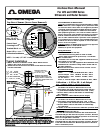
!
STATUS
Calibration
Switch
Sensor Calibration
Switch & Status Led
To Power Source
+ 8
24VDC -- 7
6
ULTRASONIC
RADAR
Connect Shield to
Ground at one End
1/2” PVC Conduit Only for PVC
Housings, Metal Conduit not
Recommended Except for
Metal Housing.
SHIELD
1) Load “Gateway PC Software” into your PC .
(Select SETUP.EXE from installation CD and follow instructions on the screen.)
2) Click on START and under PROGRAMS select “Gateway PC”.
3) Select ”Start Data Link”. You will see two bar graphs, displaying the last 8
echoes & the current output . When PC is connected to the probe, the application header displays
the Probe ID and Freq. For PC connected to the Radar the application header displays the radar
range. Traffic light icon at the bottom of the screen indicates communication status to probe.
4) Pick “Tools" and select “Show Calibration Data” .
Screen displays the following parameters,
:Reset Max. Temperature (for ultrasonic probes)
:Empty Tank Distance calibration
:Full Tank Distance calibration -programmable with accuracy of 0.1"
:Temperature Scale (for ultrasonic probes)
:Low Dielectric Material (choose for low dielectric constant materials <4)
:Pipe On/Off (select this for microwave probes operating in metal pipes)
:Select Pipe Diameter (for microwave probes only)
5) Show Calibration Data
Screen displays the following parameters,
:Sensor I.D. with single probe is 2
:Current Frequency -shows the operating frequency
:Empty Tank Distance
:Full Tank Distance
:Probe Software Rev.
:D. Link Protocol
:Max Temperature - shows the max. temperature of environment (for ultrasonic sensors only)
:Ntemp
6) Select Protocol :RS485/232
:MODBUS RTU (Holding Register address is 40109 for Radar Probes and 40080 for Ultrasonic Probes.)
7) Fix point Calibration (the same as using the probe calibration Switch ) is in the top left corner of the screen.
8) By selecting “Diagnostic” the screen displays all information on “errors”. Unhappy face icon at the screen bottom indicates sensor errors .
9) Echo chart displays information on stability of the echoes.
10) Echo Profile displays profiles of your ultrasonic probe . NOTE- when using this feature the probe is not in the measurement mode . To return to
“measurement mode” exit the echo profile (select x ). Wait until you get the Data Link OK (green light on the Probe Status LED). On the “echo profile” you
will see a marker where the software picked up an echo and the distance to the target. To change target for different measurement, exit profile screen, wait
for updated data, and go to echo profile. The marker will pick up the new target . Freeze screen and select any point on the graph by clicking mouse to
display the distance to selected target.
11) Select Data Logging Excel format (default) on FILE menu to collect history data for current and temperature in MS Excel format. Path for data collec-
tion: C:\Program Files\um_probe\GATEWAYPC\DATA\yyyy mm dd\sensorID\Data is collected for each sensor ID. The current is collected in 1 hour data
files and temperature is collected in 24 hours data files. Use chart wizard in MS Excel to create the graph and view current and temperature data. The cur-
rent data is collected every 0.5 second and temperature is collected every 1 minute.
Select Data Logging (for Sensor Viewer) on FILE menu to collect history data for current and temperature for Sensor Viewer display. Follow instruction on
Sensor Viewer Help menu.
12) Select AutoScan (only for networks) to collect data for all sensors connected in the network. Scanning time for one sensor is 30 seconds. Echo Profile
display is disabled in Auto Scan mode.
13) For low dielectric constant materials such as oils choose Low Dielectric Material “On”.
14) Select PIPE ON in Tools for microwave propagation in metal pipes, after that click on Select Pipe Diameter in Tools to choose proper diameter of metal
pipe.
Instruction Manual
For LVU and LVRD Series
Ultrasonic and Radar Sensors