


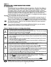
2.3.4 Strain Gauge
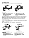
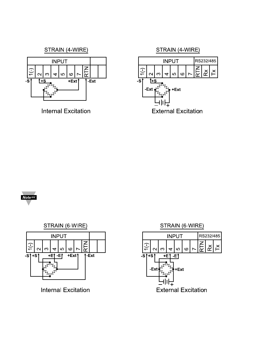
The figure below shows the wiring hookup for 4-wire bridge input.
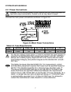
Figure 2.7
a) 4-Wire Voltage/Bridge Input b) 4-Wire Bridge Input with
with Internal Excitation External Excitation Wiring
Wiring Hookup Hookup
In 4-Wire connections the voltage drop across long excitation lead wires of strain
gauge bridge may cause measurement errors. The output of a strain gauge
bridge also depends on the stability of excitation voltage. To correct for voltage
drop and changes in excitation voltage, 6-wire input configuration and ratio
measurement are used.
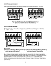
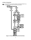
In order for the Ratiometric to work properly, the External Excitation should
not drop below 4.6 Vdc.
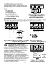
The figure below shows 6-wire hookup for 6-wire bridge input.
Figure 2.8
a) 6-Wire Bridge Input with b) 6-Wire Bridge Input with
Internal Excitation and External Excitation and
Ratio Measurement Wiring Ratio Measurement Wiring
Hookup Hookup
9