


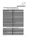

Specifications
48 900-0114-01-00 Rev A
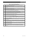
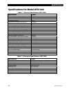
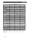
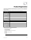
Table 17 12-Volt Inverter Settings
12 Vdc Inverter Default Minimum Maximum
Diversion On Voltage
14.6 Vdc 12 Vdc 16 Vdc
Diversion Off Delay
30 sec 0 sec 240 sec
Stacking
Stack Phase Master Master, Classic Slave, OB Slave L1, 3p Classic B,
or 3p Classic C
Power Save Level
Master Adjust Only
0 0 7
Slave Adjust Only
1 1 15
Sell
Sell RE Volts
13.0 Vdc 10 Vdc 15 Vdc
Grid Tie Window User IEEE or User
Grid Tie Authority GridTie GridTie or No Sell
Calibration (Cal)
Vac Input Adjustment
236 220 254
Vac Output Adjustment
236 220 254
Battery Vdc Adjustment
2 0 4
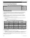
These values are in digital counts, not volts. Lower counts stand for higher voltages, and higher counts mean lower
voltages. One count equals approximately 1 Vac. The range of adjustment is 15 Vac above nominal, and 17 Vac
below nominal.
These values are in digital counts, not volts. One count equals 0.1 Vdc. The range of adjustment is 0.2 Vdc above or
below nominal.
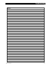
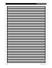
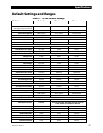
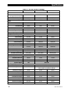
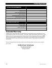
Table 18 24-Volt Inverter Settings
24 Vdc Inverter Default Minimum Maximum
Search
Search Sensitivity
(see page 14 for increments)
6 0 50
Search Pulse Length
8 4 20
Search Pulse Spacing
60 AC cycles 4 AC cycles 120 AC cycles
Input
AC Transfer Control Grid Grid or Generator
AC1/Grid Limit
50 Aac 5 Aac 60 Aac
AC2/Gen Limit
50 Aac 5 Aac 60 Aac
Inverter
Low Battery Cut-Out (LBCO)
21 Vdc 18 Vdc 24 Vdc
Low Battery Cut-In (LBCI)
25 Vdc 20 Vdc 28 Vdc
Adjust Output Voltage
120 Vac 110 vac 130 Vac
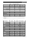
Charger
Charger Limit
11 Aac 0 Aac 12 Aac
Absorb Voltage
28.8 Vdc 26 Vdc 32 Vdc
Absorb Time Limit
1.0 hours 0.0 hours 24.0 hours
Float Voltage
27.2 Vdc 24 Vdc 30 Vdc
Float Time Period
1.0 hours 0.0 hours 24.0 hours
ReFloat Voltage
25 Vdc 24 Vdc 26 Vdc
Equalization Voltage
29.2 Vdc 28 Vdc 34 Vdc
Equalization Time Period
1.0 hours 0.0 hours 24.0 hours