


Operation
900-0114-01-00 Rev A 11
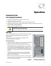
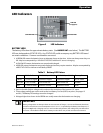
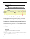
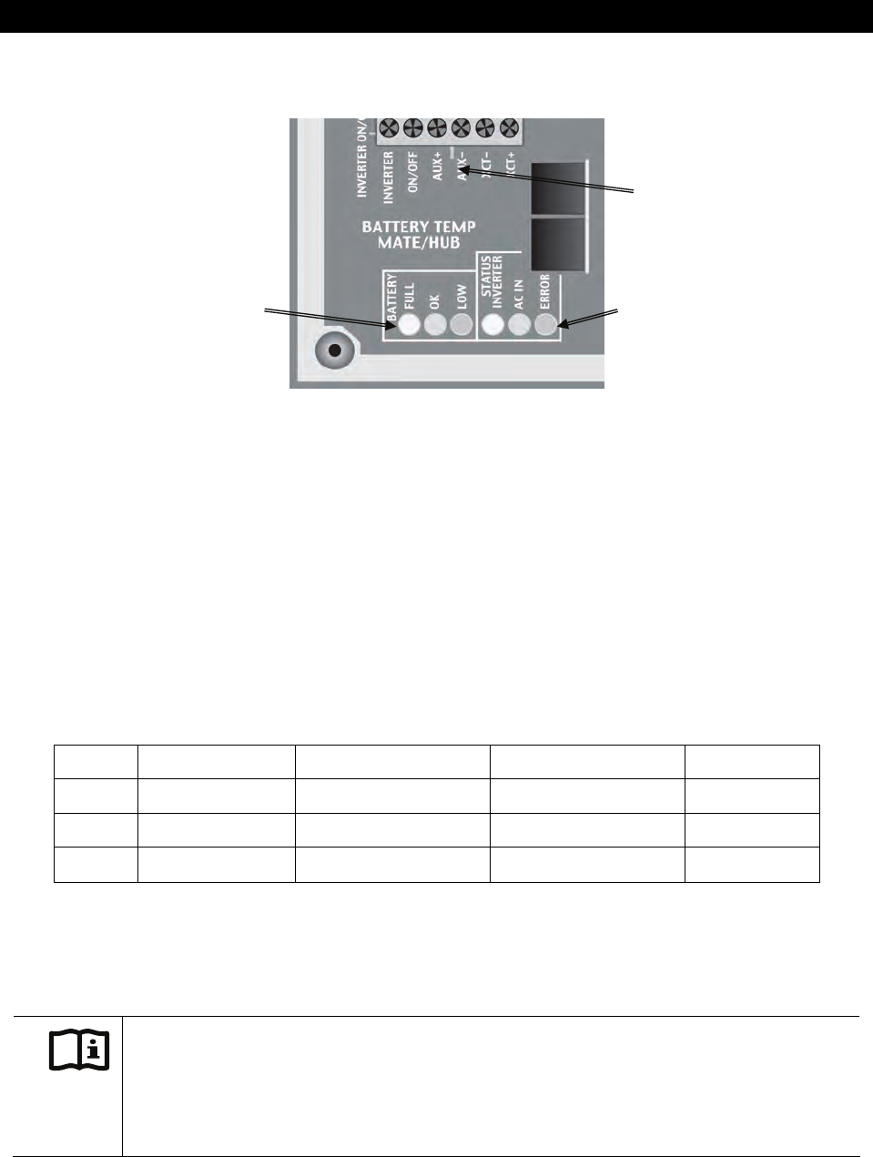
LED Indicators
Figure 3 LED Indicators
BATTERY LEDS
The battery LEDs show the approximate battery state. (See
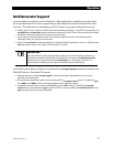
IMPORTANT
note below.) The BATTERY
LEDs are independent of STATUS LEDs. Any STATUS LED could accompany any BATTERY LED based
on certain conditions. Common combinations are noted.
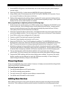
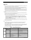
A GREEN LED means the batteries have an adequate charge at that time. It does not always mean they are
full. May be accompanied by a YELLOW STATUS LED when an AC source is charging.
A YELLOW LED means the batteries are somewhat discharged.
A RED LED means the batteries are greatly discharged and may require attention. May be accompanied by
a RED STATUS LED to indicate a Low Battery ERROR.
Table 2 Battery LED Values
Color 12 Vdc Unit 24 Vdc Unit, ± 0.2 Vdc 48 Vdc Unit, ± 0.4 Vdc Battery Status
GREEN 12.5 Vdc or higher 25.0 Vdc or higher 50.0 Vdc or higher ACCEPTABLE
YELLOW 11.5 to 12.4 Vdc 23.0 to 24.8 Vdc 46.0 to 49.6 Vdc USABLE
RED 11.4 Vdc or lower 22.8 Vdc or lower 45.6 Vdc or lower LOW
Gaps in the table (higher-voltage units) are due to the resolution of the inverter’s DC meter.
These voltage settings are not the same as the Low Battery Cut-Out (LBCO) set point. (See pages 13
and 36.) The Battery LED settings cann
ot be chang
ed.
Voltages higher than shown in the GREEN row usually means that the batteries are charging.
IMPORTANT:
Battery voltage does not always indicate an accurate state of charge. It is accurate if batteries have been
at rest for several hours at room temperature (25 °C or 77 °F, or specified by the battery manufacturer). If
they have
any
loads, a charging source, or are at another temperature, their voltage may not reflect their
true state. The OutBack FLEXnet DC is a battery monitor which can provide accurate measurements.
BATTERY LEDs STATUS LEDs
AUX LED
(see page 27)