


Operation
900-0114-01-00 Rev A 25
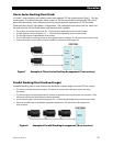
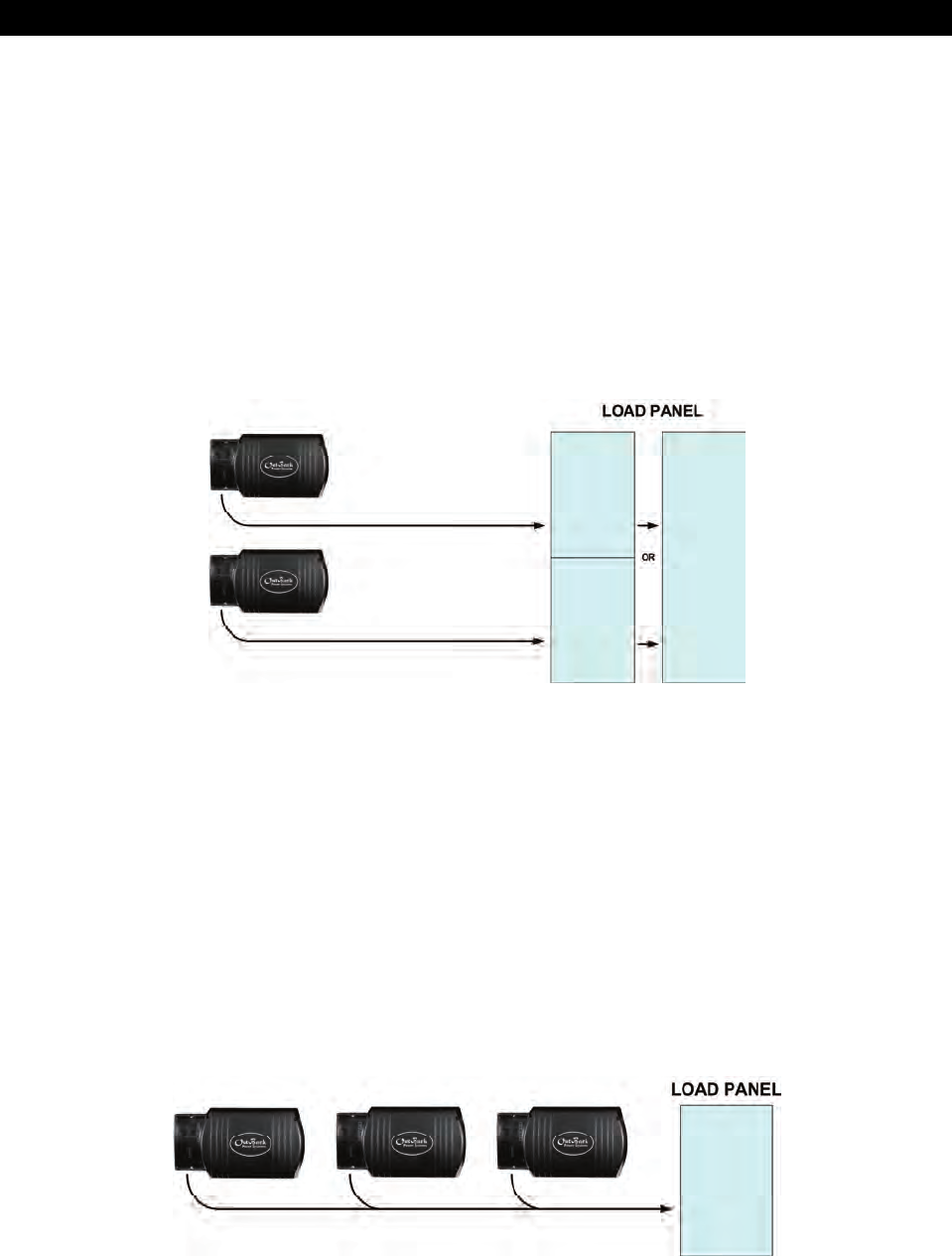
Classic Series Stacking (Dual-Stack)
In “classic” series stacking, two inverters create two separate 120 Vac output phases (“legs”). One leg
is the master. The other is the slave, which creates a 120 Vac output that is intentionally 180° out of
phase with the master. Each of these legs can be used to power a separate set of 120 Vac loads.
Collectively they form a “split-phase” configuration. This configuration produces 240 Vac, which can
be used to power 240 Vac loads when both inverters work together.
This system can continuously power 2.6 – 3.0 kVA of loads, depending on the inverter model.
A single (phase) inverter can power 1.3 – 1.5 kVA of loads, depending on the inverter model.
The two legs operate independently of each other.
The 120 Vac loads on each leg cannot exceed a given inverter’s wattage. The second inverter cannot assist.
Only two inverters, one per phase, may be installed in a classic series arrangement.
Figure 7 Example of Classic Series Stacking Arrangement (Two Inverters)
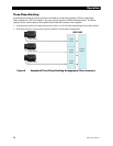
Parallel Stacking (Dual-Stack and Larger)
In parallel stacking, two or more inverters are stacked to create a single, common 120 Vac output.
The master provides the primary output. The slaves are connected to the same output and assist
the master.
The slave inverters can be programmed to activate on demand, reducing idle-power consumption. They
will remain off until the loads exceed a certain threshold.
A two-inverter system can continuously power 2.6 – 3.0 kVA of loads, depending on the inverter model.
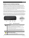
Up to ten inverters may be installed in a parallel arrangement. The example on this page shows
three inverters.
Figure 8 Example of Parallel Stacking Arrangement (Three Inverters)
1.3 kVA
120 Vac
2.6 kVA
240 Vac
1.3 kVA
120 Vac
1.3 kVA 120 Vac
1.3 kVA 120 Vac
3.9 kVA
120 Vac
1.3 kVA 120 Vac
1.3 kVA 120 Vac
1.3 kVA 120 Vac