


OEM Catalogue 2009/20103.110
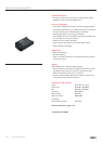
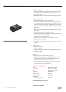
HID-DynaVision SON and CDO
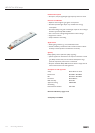
HID-DV 1-10V
HID-DV 1-10V
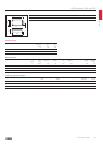
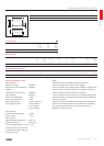
Notes:
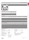
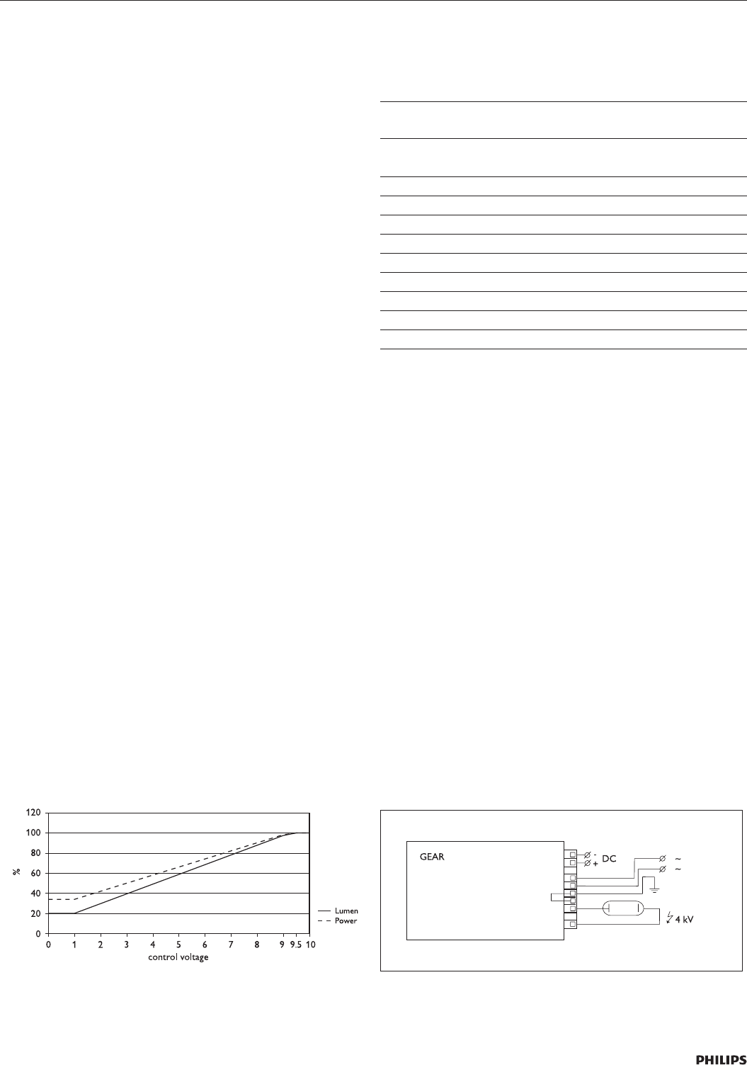
1. With three-phase mains supply, neutral should never be
disconnected; otherwise circuitry could be damaged.
2. For proper EMC, wiring inside luminaire should be as straight and as
short as possible; mains wires should not run parallel to lamp wires.
3. Driver should be mounted in luminaire > min IP 23.
4. Thermo-protected circuit incorporates self-resetting facility; ignition
attempts stop after 7 min.; mains supply must be switched off and on
to reset driver.
5. Insulation resistance test: 500 Vdc from Line/Neutral to Earth (not
between Line and Neutral). Ensure that the Neutral is reconnected
again after abovementioned test is carried out and before the
installation is put into operation.
Control Characteristics
Control input 1-10V
Control potentiometer (to be
connected on 1-10V input)
0-100kΩ
Input is protected against mains voltage connection
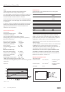
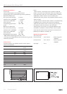
Dimming fading rates are implemented to guarantee optimal lamp
Behaviour for SON Lamps:
Run up time before dimming* 5 minutes
Fade down time** (100%-20%) < 1.5 minutes
Fade up time** (20%-100%) < 1 minute
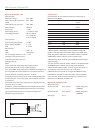
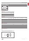
Power indication 35 - 100%
Corresponding light level (see
graph)
20% - 100%
Behaviour for CDO Lamps:
Run up time before dimming* 10 minutes
Fade down time** (100%-60%) < 1.5 minutes
Fade up time** (60%-100%) < 1 minute
Power indication 60 - 100%
Regulating light level (see graph) 50% - 100%
* EMC attention should be given with cable > 3 mtr.
** Run-up time, and fading down/up rates are determined to guarantee
reliable lamp
operations.
Inrush current
Conversion table for max. quantities of drivers on other types of
Miniature Circuit Breaker
MCB type Rating Relative number of
drivers
B 16 A 100% (see table
above)
B 10 A 63%
C 16 A 170%
C 10 A 104%
L, I 16 A 108%
L, I 10 A 65%
G, U, II 16 A 212%
G, U, II 10 A 127%
K, III 16 A 254%
K, III 10 A 154%
Notes:
1.Dataisbasedonamainssupplywithanimpedanceof400mΩ
(equal to 15 m cable of 2.5 mm
2
and other 20 m to the middle of the
power distribution), under worst case conditions. With an impedance
of800mΩthenumberofdrivercanbeincreasedby10%.
2. Measurements will be verified in real installations; therefore data are
subject to change.
3. In some cases the maximum number of drivers is not determined by
the MCB but by the maximum electrical load of the installation.
4. Note that the maximum number of drivers is given when these are
all switched on at the same moment, i.e. by a wall switch.
5. Measurements were carried out on single-pole MCB’s. For multi-
pole MCB’s it is advisable to reduce the number of drivers by 20%.
6. The maximum number of drivers which can be connected to one
Residual Current Detector of 30 mA is 30.
Mechanical installation notes
Wire cross-section:
On the mains side 0.75…2.5 mm
2
advised rating: Uo/U
= 250/250V
On the lamp side 0.75…2.5 mm
2
advised rating: Uo/U
= 250/250V
Strip length 6 mm