PS5580 RS232 and LAN Command Protocol 13
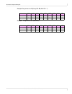
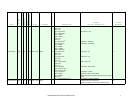
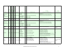
OSD V Position 0x7F Y W 4 3 0x02 = Write
Byte 1: V Position
(Range 0x00-0x64)
4
Byte 1: V Position (Range 0x00-0x64) Write 50 (0x32):
Command: 02 7F 04 01 04 02 32 03
Response: 02 7F 04 01 04 02 32 41 03
Write 50 (0x32):
Command: 02 7F 03
00 00 32 03
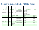
Power Off 0x11 Y RW 3 2
0x00 = Read
0x02 = Write
[None]
Write: 3 Read: 4
Byte 1: Power Status
- 0x00 = Off
- 0x01 = On
Power Off Write:
Command: 02 11 03 01 04 02 03
Response: 02 11 03 01 04 02 E2 03
Power Read (display is off):
Command: 02 11 03 01 04 00 03
Response: 02 11 04 01 04 00 00 E3 03
Power Off Write:
8
Command: 02 11 02
00 00 03
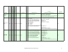
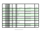
Power On 0x10 Y RW 3 2
0x00 = Read
0x02 = Write
[None]
Write: 3 Read: 4
Byte 1: Power Status
- 0x00 = Off
- 0x01 = On
Power On Write:
Command: 02 10 03 01 04 02 03
Response: 02 10 03 01 04 02 E3 03
Power Read (display is on):
Command: 02 10 03 01 04 00 03
Response: 02 10 04 01 04 00 01 E3 03
Power On Write:
8
Command: 02 10 02
00 00 03
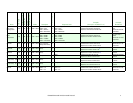
Power On Delay 0x9E Y W 4 3 0x02 = Write
Byte 1: Delay Time
(Range 0x00-0x32)
4
Byte 1: Delay Time (Range 0x00-0x32) Delay Time = 25:
Command: 02 9E 04 01 04 02 19 03
Response: 02 9E 04 01 04 02 19 3B 03
Delay Time = 25:
6
Command: 02 9E 03
00 00 19 03
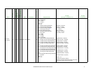
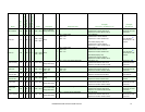
Power Save 0x63 Y W 4 3 0x02 = Write
Byte 1: Power Save
- 0x00 = Off
- 0x01 = On
4
Byte 1: Power Save
- 0x00 = Off
- 0x01 = On
Set Power Save = On:
Command: 02 63 04 01 04 02 01 03
Response: 02 63 04 01 04 02 01 8E 03
Set Power Save = On:
Command: 02 63 03
00 00 01 03
Scan Mode
(Overscan Off)
0x9B Y W 3 2 0x02 = Write [None] 3
[None] Command: 02 9B 03 01 04 02 03
Response: 02 9B 03 01 04 02 58 03
Command: 02
9B 02 00 00 03
Scan Mode
(Overscan On)
0x9A Y W 3 2 0x02 = Write [None] 3
[None] Command: 02 9A 03 01 04 02 03
Response: 02 9A 03 01 04 02 59 03
Command: 02 9A 02
00 00 03
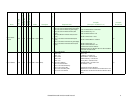
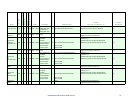
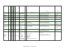
Screen Clock 0x38 Y W 4 3 0x02 = Write
Byte 1: Clock
(Range 0x00-0x64)
4
Byte 1: Clock (Range 0x00-0x64) Write 50 (0x32):
Command: 02 38 04 01 04 02 32 03
Response: 02 38 04 01 04 02 32 88 03
Write 50 (0x32)
Command: 02 38 03
00 00 32 03
Screen Clock
Phase
0x39 Y W 4 3 0x02 = Write
Byte 1: Clock Phase
(Range 0x00-0x3F)
4
Byte 1: Clock Phase (Range 0x00-0x3F) Write 32 (0x20):
Command: 02 39 04 01 04 02 20 03
Response: 02 39 04 01 04 02 20 99 03
Write 32 (0x20)
Command: 02 39 03
00 00 20 03
Screen H Position 0x36 Y W 4 3 0x02 = Write
Byte 1: H Position
(Range 0x00-0x64)
4
Byte 1: H Position (Range 0x00-0x64) Write 50 (0x32):
Command: 02 36 04 01 04 02 32 03
Response: 02 36 04 01 04 02 32 8A 03
Write 50 (0x32)
Command: 02 36 03
00 00 32 03
Name
Command
Broadcast Supported
Read/Write
Length
Length (Broadcast
Mode Data Bytes
Response Length
Response Data
Example
(Group ID = ‘A’, Multi ID = 4)
Example
(Broadcast)


