


3
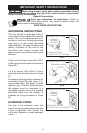
GROUNDING INSTRUCTIONS
This tool should be grounded while in
use to protect the operator from electric
shock. The tool is equipped with a 3-
conductor cord and 3-prong grounding
type plug to fit the proper grounding
type receptacle. The green (or green and
yellow) conductor in the cord is the
grounding wire. Never connect the
green (or green and yellow) wire to a live
terminal.
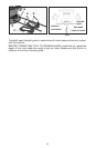
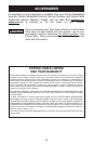
If your unit is for use on less than 150 V,
it has a plug that looks like that shown in
Figure (A).
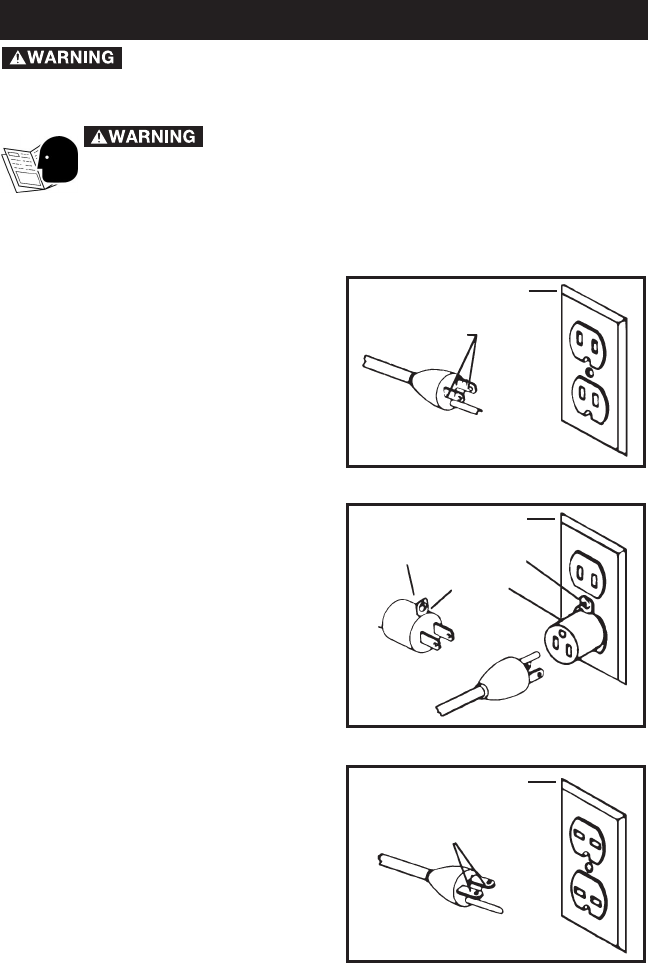
If it is for use on 150 to 250 V, it has a
plug that looks like that shown in Figure
(C).
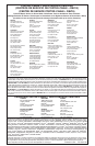
An adapter, see Figure (B) is available for
connecting Figure (B) type plugs to 2-
prong receptacles. The green- colored
rigid ear, lug, or the like, extending from
the adapter must be connected to a
permanent ground, such as a properly
grounded outlet box. No adapter is
available for a plug as shown in Figure
(C).
EXTENSION CORDS
Use only 3-wire extension cords that
have 3-prong grounding-type plugs and
3-pole receptacles that accept the
tool’s plug. Replace or repair damaged
cords.
GROUNDED OUTLET BOX
Fig. A
Fig. B
Fig. C
CURRENT
CARRYING
PRONGS
GROUNDING PRONG
IS LONGEST OF THE 3 PRONGS
GROUNDED OUTLET BOX
GROUNDED OUTLET BOX
GROUNDING MEANS
ADAPTER
CURRENT
CARRYING
PRONGS
GROUNDING PRONG
IS LONGEST OF THE 3 PRONGS
Read and understand all instructions. Failure to
follow all instructions listed below, may result in electric shock, fire
and/or serious personal injury.
SAVE THESE INSTRUCTIONS.
IMPORTANT SAFETY INSTRUCTIONS
When using electric tools, basic safety precautions should
always be followed to reduce the risk of fire, electric shock, and personal
injury, including the following:
Read All Instructions.