


8
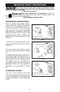
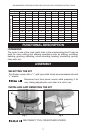
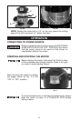
1. To remove motor unit from base unit: Open the clamp (A) Fig. 1. While
holding base, turn power unit COUNTERCLOCKWISE until lower pin (B) in
motor housing is disengaged from groove in base. Lift power unit free from
base unit.
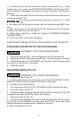
2. Clean and insert shank of bit into collet until shank bottoms, then back it
out approximately 1/16".
Do not use router bits with a diameter in excess of 1.5" in this
tool.
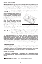
3. Lay power unit on its side on bench with the collet pointing AWAY from
you.
4. Place one wrench on flats of chuck with the opposite end of the wrench
resting on the bench to your left (Fig. 2).
5. Place other wrench on collet and tighten COUNTERCLOCKWISE.
TIGHTEN FIRMLY.
6. To remove the bit, reverse the procedure.
AVOID POSSIBLE DAMAGE TO COLLET. NEVER TIGHTEN COLLET WITHOUT BIT.
ATTACHING THE MOTOR TO THE ROUTER BASE
DISCONNECT TOOL FROM POWER SOURCE.
1. Open the clamp (A) Fig. 1 and set the power unit in the base unit.
2. Align the lower pin of the power unit (B) Fig. 1 with the groove in the base.
3. Rotate the power unit CLOCKWISE into the base until the upper guide
pins are set in the groove of the base.
4. Close the clamp.
ADJUSTING DEPTH OF CUT
DISCONNECT TOOL FROM POWER SOURCE.
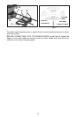
1. Open the clamp (A) Fig. 3A.
2. Hold the base (E) and turn the power unit (F) Fig. 3A COUNTER-CLOCK-
WISE until the tip of the bit is above the bottom of the base.
3. Set the tool on a flat surface.
4. Turn the power unit (F) Fig. 3A CLOCKWISE until bit touches the work.
5. Close the clamp (A) Fig. 3A.
6. Rotate the depth adjusting ring (B) Fig. 3A until the zero-line (C) Fig. 3B
is opposite the index line (D) Fig. 3B on the housing.
7. Open the clamp (A) Fig. 3A.
8. Tip the router so that the bit is clear of the wood surface. Turn the power
unit (F) Fig. 3A CLOCKWISE until the index line (D) Fig. 3B on the motor
housing reaches the desired depth indicated on the ring.
9. Close the clamp (A) Fig. 3A.