19
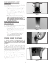
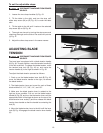
Fig. 47
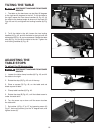
To set the adjustable stops:
1. Loosen the two clamp handles (A) Fig. 43.
2. Tilt the table to the right, and turn the stop until
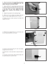
either stop screw (M) or (N) Fig. 48, is under the table
skirt.
3. Tilt the table to the left until it rests on the selected
stop screw (M) or (N) Fig. 48.
4. The angle can be set by turning the stop screw and
checking the angle on the side of the scale with pointer
(J) Fig. 47.
5. Adjust the other stop screw in the same manner.
Fig. 48
DISCONNECT MACHINE FROM POWER
SOURCE.
ADJUSTING BLADE
TENSION
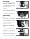
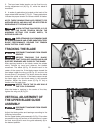
The band saw is equipped with a blade tension handle
(A) Fig. 49. To apply tension, move the tension handle (A)
to the left as shown. To release the blade tension, move
the tension lever lock (B) Fig. 49 up, and move the
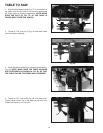
tension handle (A) to the right as shown in Fig. 50.
To adjust the blade tension proceed as follows:
1. Push up on the blade tension lever lock (B) Fig. 49,
move the blade tension handle to the right, to remove
the blade tension.
2. The blade tension lever can be set for each of these
blade widths 3/4", 1/2", 3/8", 1/4", and 1/8".
3. Make sure the blade tension lever is rotated to the
right as far as possible. Pull out on the blade tension
handle (A) Fig. 50, and turn the the tension lever until the
appropriate width of the blade is shown on the top of the
blade tension lever scale (C) and then release the blade
tension lever handle so that the handle is contacting the
hub (D).
4. Move the blade tension lever to the left until the lever
lock (B) Fig. 49 engages the blade tension lever handle
(A).
DISCONNECT MACHINE FROM POWER
SOURCE.
Fig. 49
Fig. 50
M
N
J
K
A
B
A
C
D


