


10
Fig. 4A
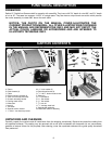
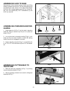
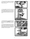
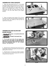
ASSEMBLING LEGS TO BASE
Mechanically lift the machine using a forklift and lifting
straps to support the machine. The four steel legs should
be attached to each corner of the base using sixteen
5/16-18 x 5/8" carriage head screws (A) Fig. 4A and Fig.
4B, 5/16" flat washers (B), 5/16" lockwashers (C) and
5/16" hex nuts (D).
Fig. 5
Fig. 6
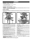
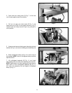
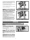
ASSEMBLING OVERARM ELEVATING
HANDLE
1. Insert shear pin (A) Fig. 5, into the hole in elevating
shaft (B). Using a hammer, tap this pin in to place as
show in Fig. 5.
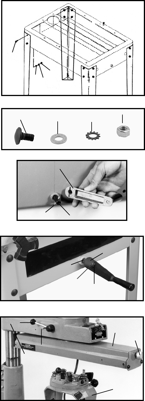
2. Line up the slots in elevating handle (C) Fig. 5, with
shear pin (A) and place handle on shaft (B) making
certain the roll pin is engaged in the slots.
3. Fasten elevating handle (C) Fig. 6, to shaft (B) with
a 1/4"-20 x 1/2" hex head screw (D) and 1/4" flat washer
(E).
A
B
C
Fig. 4B
A
B
C
D
A
B
C
D
B
C
D
E
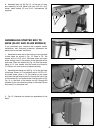
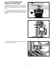
ASSEMBLING CUTTINGHEAD TO
TRACK ARM
1. Raise the track arm assembly (A) Fig. 7, by turning
overarm elevating handle (F) Fig. 2.
2. Remove packing material from around cuttinghead
assembly (B) Fig. 7.
Fig. 7
C
D
A
F
E
B