


9
ASSEMBLY
ASSEMBLY TOOLS REQUIRED
ASSEMBLY TIME ESTIMATE - 2-3 hrs.
* Blade wrenches (supplied)
*
1
/2” and
3
/8” open end or socket wrenches (not included)
*
5
/16” hex wrench (not included)
* Flat screwdriver and hammer (not included)
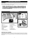
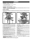
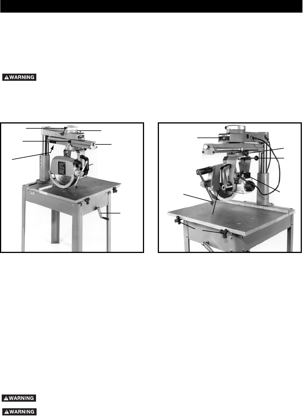
The following is an explanation of the operating controls of the Delta 12” Radial Saw. We suggest you study these
explanations carefully to familiarize yourself with the controls before turning on the power, to avoid damage to the saw
or personal injury.
A – TRACK ARM CLAMP KNOB. Controls swing of track arm
for all miter cutting operations. Locks track arm at any angle for
the full 360º rotation. To rotate track arm loosen clamp knob
and rotate arm. The arm will stop at the 0º and 45º positions
right and left. To move the arm past these points the track arm
index knob (B) must be pulled out. (Fig. 2)
B – TRACK ARM INDEX KNOB. Locates 0º and 45º position,
right and left, of the track arm. (Fig. 2)
C – YOKE INDEX LEVER. Locates each 90º position of the
yoke for ripping or cross-cutting operations. When rotating the
yoke the yoke clamp handle must first be loose. (Fig. 2)
D – YOKE CLAMP HANDLE. The yoke clamp handle must be
loose when rotating the yoke to the rip or cross-cut position.
(Fig. 3)
E – ANTI-KICKBACK DEVICE. When ripping, the yoke is po-
sitioned and clamped so that the blade is parallel to the fence.
The infeed side of the blade guard is lowered until it almost
touches the workpiece. The anti-kickback rod is then lowered
so that the fingers catch and hold the workpiece. Never rip
from the anti-kickback end of the blade guard. (Fig. 3)
F – OVERARM ELEVATING HANDLE. Controls the depth of
cut in all operations. Turning the handle raises or lowers the
overarm. (Fig. 2)
G – CUTTINGHEAD CLAMP KNOB. Locks cuttinghead at any
position on the track arm. When ripping the cutting clamp knob
must be tight. (Fig. 3)
H – BEVEL INDEX KNOB. Locates 0º and 45º and 90º
positions of the motor when bevel cutting. When tilting the
motor for bevel cutting, the bevel clamp handle must first be
loose. (Fig. 3)
J – BEVEL CLAMP LEVER. Controls tilt of motor for bevel
cutting operations. Locks motor at any desired angle on the
bevel scale. (Fig. 3)
K – TABLE CLAMP KNOBS. Allows the operator to quickly set
the desired fence position. (Fig. 3)
L – ON-OFF SWITCH. Conveniently placed at eye level; switch
can be turned on or off in an instant for added operator
protection. (Fig. 3)
M – MITER SCALE. Indicates degrees left and right for setting
track arm. (Fig. 2)
N – TRACK ARM STOP. (Located under the track arm.). See
(A) Fig. 58 on Page 24 for illustration. This stop prevents the
blade from contacting column when making straight cut-offs
with the motor tilted for a 45 degree bevel cut.
Fig. 2
Fig. 3
A
C
M
B
F
L
E
H
J
D
G
K
GUIDE TO PARTS
N
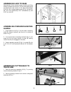
THE 12" RADIAL ARM SAW IS VERY HEAVY AND REQUIRES SEVERAL PEOPLE TO LIFT AND
MANUEVER IT DURING ASSEMBLY.
DO NOT OPERATE THIS MACHINE UNTIL YOU READ AND UNDERSTAND THE ENTIRE
INSTRUCTION MANUAL.
DISCONNECT MACHINE FROM POWER SOURCE.