


10
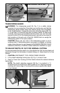
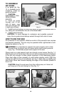
3. Turn saw upside down, retract telescoping guard and check 45° angle as
shown in Fig. 8.
4. If adjustment is necessary loosen bevel adjustment locking lever and turn
stop screw until angle is correct.
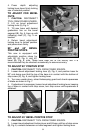
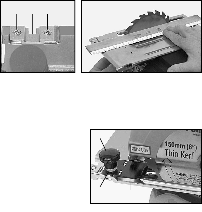
LINE OF CUT INDICATOR
A line of cut indicator (A), Fig. 9, is provided at the front of the base. The left
edge of the notch in this indicator is used to follow a line when making 90°
cuts. The right edge of the notch is used to follow a line when making 45°
cuts. This indicator may be adjusted as follows:
1. CAUTION: DISCONNECT TOOL FROM POWER SOURCE.
2. Adjust saw for 90° cut.
3. Loosen two screws (B), Fig. 9.
4. Place a straight edge along side of blade touching set of blade teeth at
both front and rear of blade as shown in Fig. 9A.
CAUTION: Avoid contact with blade teeth to prevent personal injury.
5. Align left edge of notch in indicator with straight edge and tighten two
screws (B), Fig. 9.
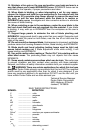
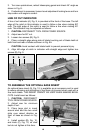
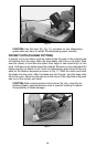
TO ASSEMBLE THE OPTIONAL BASE INSERT
An optional base insert (A), Fig. 10, is available as an accessory and is used
to reduce chipping and splintering of top fibers of plywood when used with a
fine tooth blade. THIS INSERT CANNOT BE USED WHEN MAKING BEVEL
CUTS. Install insert as follows:
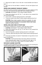
1. CAUTION: DISCONNECT
TOOL FROM POWER SOURCE.
2. Adjust saw for minimum
depth of cut.
3. Place large slot in insert
around stud and the two small
slots over raised dimples on
front of base as shown in Fig.
10.
4. Install washer (B), Fig. 10,
and knob (C), Fig. 10, on stud
but do not tighten at this time.
Fig. 9 Fig. 9A
A
B
B
Fig. 10
C
A
B