


9
4. Press depth adjusting
locking lever down firmly locking
saw in selected position.
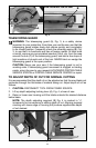
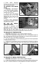
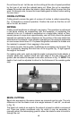
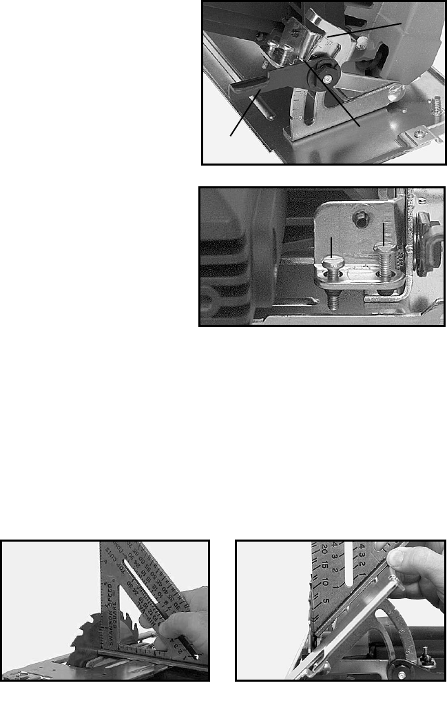
TO ADJUST FOR BEVEL
CUTS
1. CAUTION: DISCONNECT
TOOL FROM POWER SOURCE.
2. Lift up bevel adjustment
locking lever (A), Fig. 5.
3. Tilt saw base until desired
graduation line on the bevel
segment (B), Fig. 5, lines up with
indicating mark (C), Fig. 5 on
bracket.
4. Return bevel adjustment
locking lever to locked position
and press down firmly.
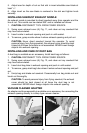
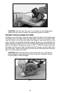
90° and 45° BEVEL
POSITIVE STOPS
This saw is equipped with
adjustable positive stops for
both 90° (A), Fig. 6, and 45°
bevel (B), Fig. 6, cuts. These have been set at the factory and it is
recommended they be checked occasionally to assure accuracy.
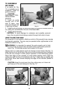
TO ADJUST 90° POSITIVE STOP
1. CAUTION: DISCONNECT TOOL FROM POWER SOURCE.
2. Loosen bevel adjustment locking lever (A), Fig. 5, and position base for
90° cuts being sure that the top of the base is in contact with the bottom of
stop screw (A), Fig. 6, and tighten locking lever.
3. Turn saw upside down, retract telescoping guard and check squareness
of blade as shown in Fig. 7.
4. If adjustment is necessary loosen bevel adjustment locking lever, keeping
top of base in contact with stop screw, turn stop screw until squareness is
obtained.
TO ADJUST 45° BEVEL POSITIVE STOP
1. CAUTION: DISCONNECT TOOL FROM POWER SOURCE.
2. Loosen bevel adjustment locking lever and tilt base until top of stop screw
(B), Fig. 6, contacts extension on bevel segment and tighten locking lever.
Fig. 5
B
A
C
Fig. 6
B
A
Fig. 7 Fig. 8