12
1.
Remove the power unit from the base unit (see “TO INSTALL BIT”).
2. Install the bit.
3.
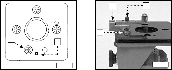
The base and roller guide (A) Fig. 5 is assembled at the factory. To install,
remove a sub-base mounting screw (A) Fig. 6 and insert the alignment pin (in
the guide base) into the hole (C) in the bottom of the trimmer sub-base. Fasten
with two mounting screws (F) Fig. 5 and (C) Fig. 7. Hand tighten for further
adjustment.
4. Install the bit (See “TO INSTALL THE BIT.”). Then, install the motor to base
and adjust the depth of cut (See “ADJUSTING DEPTH OF CUT”).
5. Align the roller guide with the bit by loosening the locking screw (A) Fig. 7 and
turning the adjusting screw (B) with the provided hex wrench until the guide is
in the desired location.
ATTACHING AND ADJUSTING THE BASE AND THE ROLLER GUIDE
FLUSH TRIMMING
Fig. 6
C
A
1. Attach the base and guide to the trimmer as outlined in "ATTACHING AND
ADJUSTING THE BASE AND ROLLER".
2. Remove the roller guide and replace it with the flush trimming guide (B) Fig.
4. Identify this guide by the molded letter “F”. Make sure that the stud on the
end of this guide faces the trimmer base.
3. Install the guide setting gauge (E) Fig. 4 in the trimmer collet (see "TO
INSTALL THE BIT"). Install the trimmer motor to the base. Adjust the guide
so that hole in the end of the gauge is positioned over the guide stud.
4. Remove the guide setting gauge from the trimmer and install a flush
trimming bit.
5. Adjust the depth of cut so that the straight portion of the bit extends below
the trimmer base at least the thickness of the workpiece.
6. Make a trial cut on scrap material.
A
B
C
Fig. 7
BEVEL TRIMMING
1. Follow Steps 1 through 5 under "FLUSH TRIMMING", except install the
bevel trimming guide (C) Fig. 4. This guide is identified by the molded letter
“B”.
2. Adjust the depth of cut so that only the bevel portion of the bit extends
below the trimmer base at least the thickness of the material to be trimmed.
3. Make a trial cut on scrap material to check alignment.


