


Fig. 6
8
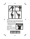
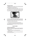
SPINDLE LOCK
A spindle lock (A) Fig. 5 is
located on the right side of the
gear case. To Operate: Depress
spindle lock pin with thumb
while rotating spindle (B) BY
HAND until pin engages and
stops spindle rotation.
CAUTION: Do not depress
spindle lock while tool is
running.
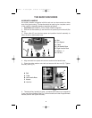
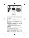
THE DISC SANDER
TO INSTALL SANDING DISC
The Porter-Cable sander has a wrenchless type backup pad and locknut. No
wrenches are required to install or remove sanding disc.
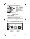
1. CAUTION: DISCONNECT TOOL FROM POWER SOURCE.
2. Depress spindle lock pin (see Fig. 6) and rotate back-up pad clockwise
onto spindle until it seats. Then rotate the flexible disc onto shaft until it seats.
3. Place retaining nut through hole in sanding disc and rotate clockwise onto
shaft until it seats. Normal operation of the Sander will tighten the sanding
disc.
4. To remove sanding disc, disconnect machine from power source, depress
spindle lock pin and rotate sanding disc together with the flexible disc
counterclockwise and remove.
Fig. 5
A
B
A
B
C
D
E
F
A Spindle Lock Pin
B Spindle
C Back-up Pad
D Flexible Disc
E Sanding Disc
F Retaining Nut
892459 - 11-30-00.QXD 2/25/02 8:23 AM Page 8