


10
TO INSTALL GRINDING WHEEL
DISCONNECT TOOL FROM POWER SOURCE.
1. Rest the tool on its back with the spindle facing up.
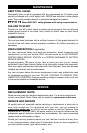
2. Install and adjust the appropriate wheel guard following instructions in
“TO INSTALL WHEEL GUARD” section of this manual.
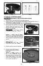
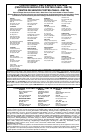
3. Position the inner flange (A) Fig. 5 on
the spindle (C) with the round hub
facing outward, away from tool.
Rotate the flange until it drops into
place on the spindle.
Use Type 1 Wheel
Guard when using Type 1 Wheels.
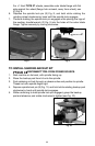
NOTE: For TYPE 1 Blades ONLY:
reverse the inner flange and assemble
it to the spindle with the round hub
facing inward, toward the tool (see A
Fig. 6).
Use Type 1 Blade
Guard when using Type 1 Blades.
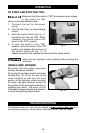
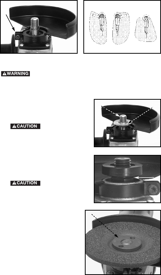
4. Position grinding wheel to spindle.
5. Position outer blade flange to
spindle and thread into place
hand tight.
NOTE: For TYPE 1 wheels, and
for
1
/4" thick TYPE 27 wheels,
assemble with the hub side of the
outer blade flange in the wheel
bore (flat side of flange out, away
from wheel), see (B) Fig. 7.
Fig. 3
A
Fig. 4
Fig. 5
A
C
Fig. 6
A
B
Fig. 7