


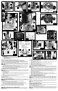
PLUNGE BASE
1. Open the clamp (I) FIg. 5 and set the motor in the base.
2. Align the rack and pin (C) Fig. 1 of the motor with the grooves in the base. Lower the
motor into the base.
3. Close the clamp (I) Fig. 5.
NOTE: Reverse procedure for both bases to remove the motor.
ADJUSTING ALIGNMENT ON ACCESSORY SUB-BASE (FOR FIXED BASE ONLY)
The sub-base for the 890 fixed base model can be replaced with an accessory sub-base that is
suitable for use with template guides. If you replace the standard sub-base with another, you will
need to be sure the sub-base is aligned to the collet. To do this:
To reduce the risk of injury, turn unit off and disconnect it from power source before
installing and removing accessories, before adjusting or when making repairs. An accidental start-
up can cause injury.
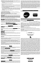
1. Remove the standard large-hole sub-base by removing three screws (A) Fig. 4A. Replace with
accessory sub-base (Fig. 4B), but do not fully tighten screws (A).
2. Open the clamp and adjust the power unit so that the collet nut (A) engages the center hole in
the sub-base (C). Allow the sub-base to center itself on the collet nut. Close the clamp.
3. Tighten the sub-base mounting screws (B) Fig. 4 securely.
ADJUSTING THE DEPTH OF CUT (FIXED BASE ONLY)
To reduce the risk of injury, turn unit off and disconnect it from power source before
installing and removing accessories, before adjusting or when making repairs. An accidental start-up
can cause injury.
1. Open the clamp (A) Fig. 3.
2. Pull the lever (B) and set the router on the workpiece. With the router flat and level, let the bit barely
touch the workpiece.
3. Hold the lever (B) and turn the depth knob (C) until the zero aligns with the zero mark on the router
base.
4. Release the lever (B). Make sure that the zero remains aligned with the zero mark.
5. Turn the knob (C) clockwise to the desired depth of cut.
6. Close the clamp (A).
NOTE: Setting the index line to 1/16" (
1.6 mm)
on the knob indicates that the cutting edge of the bit is
exposed 1/16" (
1.6 mm)
below the base.
DUST EXTRACTION (PLUNGE BASE ONLY)
To reduce the risk of injury, turn unit off and disconnect it from power source before
installing and removing accessories, before adjusting or when making repairs. An accidental start-up
can cause injury.
To connect the router to a vacuum cleaner for dust extraction, follow these steps:
1. Remove the dust cap (E) Fig. 6 by pulling straight up.
2. Insert the dust extraction hose adapter (F) into the dust extraction port (G) as shown.
3. Insert the end of a standard vacuum cleaner tube (H) into the hose adapter.
4. When using dust extraction, be aware of the placement of the vacuum cleaner. Be sure that
the vacuum cleaner is stable and that its hose will not interfere with the work.
NOTE: Be sure the dust shroud (S) Fig. 5 is installed into the plunge base as shown.
INSTALLING AND REMOVING THE BIT (PLUNGE BASE ONLY)
To reduce the risk of injury, turn unit off and disconnect it from power source before
installing and removing accessories, before adjusting or when making repairs. An accidental start-
up can cause injury.
To remove the motor unit from the base:
1. Pull the lever (I) Fig. 5 toward you.
2. Remove the power unit from the base.
3. Clean and insert the shank of the bit into the collet until the shank bottoms, then back it out
approximately 1/16" (
1.6 mm)
.
4. Lay the power unit on its side on a bench with the collet pointing AWAY from you.
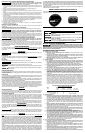
5. Press the spindle lock button (A) Fig. 2.
6. Place the wrench on the collet and turn CLOCKWISE to tighten. Tighten firmly.
7. To remove the bit, reverse the procedure.
ADJUSTING THE DEPTH OF CUT (PLUNGE BASE ONLY)
To reduce the risk of injury, turn unit off and disconnect it from power source before
installing and removing accessories, before adjusting or when making repairs. An accidental start-up
can cause injury.
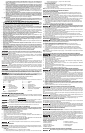
1. Loosen the depth rod locking knob (J) Fig. 6, and depth indicator knob (K), allowing the depth
rod (L) to contact one of the turret stops (M) Fig. 7. Normally the deepest desired cut is set with
the depth rod resting on the lowest point on the turret dial (N) Fig. 6. You can also utilize any
combination of fixed and/or adjustable stops (M) to achieve the desired depth of cut.
2. Push the router down until the bit touches the work surface. Push the locking lever (O) down to
lock the router in this position.
3. Tighten the depth-rod locking knob (J) Fig. 6.
4. Position the depth indicator (P) Fig. 8 at the “0” position and tighten the knob (K) Fig. 8.
5. Loosen the depth-rod locking knob (J) Fig. 6, and raise depth rod (L) until the indicator (P) Fig.
8 aligns with the desired depth of plunge measurement (R).
6. Tighten the depth-rod locking knob (J) Fig. 6.
STARTING AND STOPPING THE MOTOR (ALL UNITS)
Before starting the tool, clear the work area of all foreign objects. Keep a firm grip
on the tool to resist starting torque. Two switches (A and B) Fig. 9 turn this tool “ON” and “OFF”.
The upper switch (A) will automatically turn the tool “OFF” if the tool is placed upside down on a
surface.
Turn the tool “ON” or “OFF” with lower switch (B), using the thumb of the left hand while holding
the tool.
To avoid injury and/or damage to finished work, always allow the motor to come to a
COMPLETE STOP before putting the tool down.
NOTE: For convenient debris collection, you can attach a shop vac to the GripVac™ unit by
placing the hose on the GripVac handle Fig. 17.
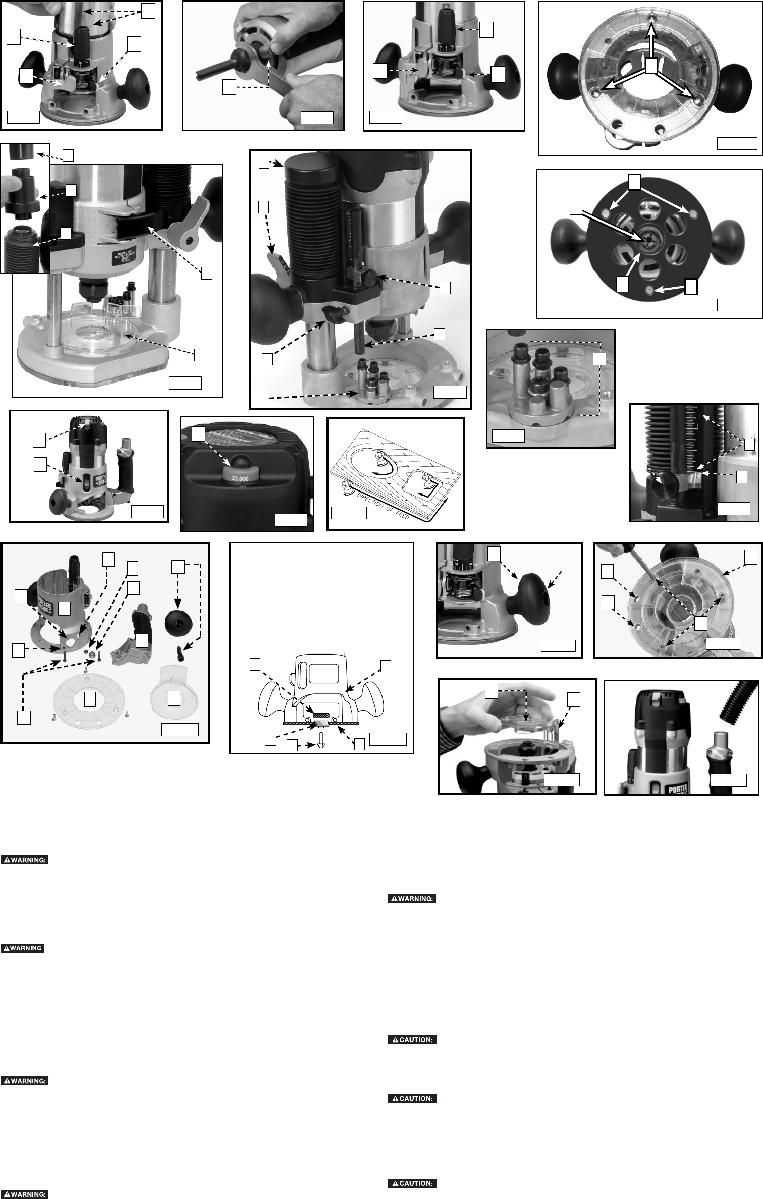
VARIABLE SPEED CONTROL (ALL UNITS)
This router is equipped with a variable speed control (A) Fig. 10 with an infinite number of speeds
between 10,000 and 23,000 RPM.
Adjust the speed by turning the speed control knob (A).
In low and medium speed operation, the speed control prevents the motor speed
from decreasing. If you expect to hear a speed change and continue to load the motor, you could
damage the motor by overheating. Reduce the depth of cut and/or slow the feed rate to prevent
tool damage.
A
B
C
Fig. 1
Fig. 11
A
SCREW
Fig. 14
A
A
D
Fig. 7
Fig. 8
Fig. 17
A
Fig. 2
Fig. 3
A
B
C
M
K
P
Fig. 9
A
B
Fig. 10
Fig. 15
B
A
E
B
Fig. 16
J
C
H
D
E
F
G
B
A
K
L
C
D
O
J
K
L
N
Fig. 6
R
Fig. 12
Fig. 4B
Fig. 4A
A
A
A
B
C
Fig. 5
H
F
G
E
S
I
Fig. 13
5
4
1
3
2
1. ROUTER BASE
2. SUB-BASE
3. ROUTER BIT
4. TEMPLET GUIDE
5. LOCKNUT
1. BASE DE LA TOUPIE
2. SOUS-BASE
3. MÈCHE DE TOUPIE
4. GUIDE DE GABARIT
5. CONTRE-ÉCROU
1. BASE DEL REBAJADORA
2. SUB-BASE
3. BROCA
4. GUIA DE PATRON
5. TUERCA INAFLOJABLE