


MESURES DE SÉCURITÉ - DÉFINITIONS
Indique une situation dangereuse imminente qui, si elle n’est pas évitée,
causera la mort ou des blessures graves.
Indique une situation potentiellement dangereuse qui, si elle n’est
pas évitée, pourrait se solder par un décès ou des blessures graves.
Indique une situation potentiellement dangereuse qui, si elle n’est pas
évitée pourrait se solder par des blessures mineures ou modérées.
Utilisé sans le symbole d’alerte à la sécurité, indique une situation
potentiellement dangereuse qui, si elle n'est pas évitée pourrait se solder par des
dommages à la propriété.
Règles Générales Sur la Sécurité
Lire toutes les directives. Tout manquement aux directives suivantes pose des
risques de choc électrique, d’incendie et/ou de blessure grave. Le terme « outil électrique » dans tous
les avertissements ci-après se rapporte à votre outil électrique à alimentation sur secteur (avec fi l) ou
par piles (sans fi l).
CONSERVER CES DIRECTIVES
1) Sécurité du lieu de travail
a) Tenir la zone de travail propre et bien éclairée. Les lieux encombrés ou sombres sont
propices aux accidents.
b) Ne pas faire fonctionner d’outils électriques dans un milieu défl agrant, soit en pré-
sence de liquides, de gaz ou de poussières infl ammables. Les outils électriques produi-
sent des étincelles qui peuvent enfl ammer la poussière ou les vapeurs.
c) Éloigner les enfants et les personnes à proximité pendant l’utilisation d’un outil élec-
trique. Une distraction pourrait vous en faire perdre la maîtrise.
2) Sécurité en matière d’électricité
a) La fi che de l’outil électrique doit être compatible avec la prise de courant. Ne modifi ez
jamais la fi che de quelque façon que ce soit. N’utilisez jamais d’adaptateurs de fi ches
avec des outils électriques mis à la terre. Le risque de choc électrique sera réduit par
l’utilisation de fi ches non modifi ées et de prises de courant compatibles.
b) Éviter tout contact physique avec des surfaces mises à la terre comme des tuyaux,
des radiateurs, des cuisinières et des réfrigérateurs. Le risque de choc électrique est
plus élevé si votre corps est mis à la terre.
c) Ne pas exposer les outils électriques à la pluie ou à l’humidité. La pénétration de l’eau
dans un outil électrique augmente le risque de choc électrique.
d) Ne pas utiliser le cordon de façon abusive. Ne jamais utiliser le cordon pour trans-
porter, tirer ou débrancher un outil électrique. Tenir le cordon éloigné de la chaleur,
de l’huile, des bords tranchants ou des pièces mobiles. Les cordons endommagés ou
enchevêtrés augmentent les risques de choc électrique. Utiliser uniquement une rallonge à
3 fi ls pourvue d’une fi che de mise à la terre à 3 lames et une prise à 3 fentes correspondant
à la fi che.
e) Pour l’utilisation d’un outil électrique à l’extérieur, se servir d’une rallonge convenant
à une telle utilisation. Si la rallonge sera utilisée à l’extérieur, elle doit être estampillée d’un
W-A ou d’un W suivi de la classifi cation de la rallonge. L’utilisation d’une rallonge conçue
pour l’extérieur réduit les risques de choc électrique. Lorsque qu’une rallonge électrique est
utilisée, s’assurer d’en utiliser une de calibre suffi samment élevé pour assurer le transport
du courant nécessaire au fonctionnement de l’appareil. Un cordon de calibre inférieur cau-
sera une chute de tension de ligne et donc une perte de puissance et une surchauffe. Le ta-
bleau suivant indique le calibre approprié à utiliser selon la longueur du cordon et l’intensité
nominale de la plaque signalétique. En cas de doute, utiliser le calibre suivant le plus gros.
Plus le numéro de calibre est petit, plus le cordon est lourd.
Calibre de fil minimum recommandé pour les rallonges
Volts Longueur totale de la rallonge
120V 0-25 pi 26-50 pi 51-100 pi 101-150 pi
0-7.6 m 7.6 m - 15.2 m 15.2 m - 30.5 m 30.5 m - 45.7 m
Amperes Calibre de fil dans des unités d’A.W.G.
De 10 a 12 ampères 16 16 14 12
“ 12 a 16 ampères 14 12 not recommended
3) Sécurité personnelle
a) Être vigilant, surveiller le travail effectué et faire preuve de jugement lorsqu’un outil
électrique est utilisé. Ne pas utiliser d’outil électrique en cas de fatigue ou sous l’in-
fl uence de drogues, d’alcool ou de médicaments. Un moment d’inattention, durant l’uti-
lisation d’un outil électrique, peut se solder par des blessures graves.
b) Utiliser un équipement de sécurité. Toujours porter une protection oculaire. L’utili-
sation d’un équipement de sécurité comme un masque anti-poussières, des chaussures
antidérapantes, un casque de sécurité ou des protecteurs auditifs lorsque la situation le
requiert réduira les risques de blessures corporelles.
c) Éviter un démarrage accidentel. S’assurer que l’interrupteur se trouve à la position
d’arrêt avant de brancher l’outil. Transporter un outil électrique alors que le doigt repose
sur l’interrupteur ou brancher un outil électrique dont l’interrupteur est à la position de mar-
che risque de provoquer un accident.
d) Retirer toute clé de réglage ou clé standard avant de démarrer l’outil. Une clé standard
ou une clé de réglage attachée à une partie pivotante de l’outil peut provoquer des blessu-
res corporelles.
e) Ne pas trop tendre les bras. Conserver son équilibre en tout temps. Cela permet de
mieux maîtriser l’outil électrique dans les situations imprévues.
f) S’habiller de manière appropriée. Ne pas porter de vêtements amples ni de bijoux.
Garder les cheveux, les vêtements et les gants à l’écart des pièces mobiles. Les vête-
ments amples, bijoux ou cheveux longs pourraient s’enchevêtrer dans les pièces mobiles.
g) Si des composants sont fournis pour le raccordement de dispositifs de dépoussiéra-
ge et de ramassage, s’assurer que ceux-ci sont bien raccordés et utilisés. L’utilisation
de ces dispositifs peut réduire les risques engendrés par les poussières.
4) Utilisation et entretien d’un outil électrique
a) Ne pas forcer un outil électrique. Utiliser l’outil électrique approprié à l’application.
L’outil électrique approprié effectuera un meilleur travail, de façon plus sûre et à la vitesse
pour laquelle il a été conçu.
b) Ne pas utiliser un outil électrique dont l’interrupteur est défectueux. Tout outil électri-
que dont l’interrupteur est défectueux est dangereux et doit être réparé.
c) Débrancher la fi che du bloc d’alimentation avant de faire quelque ajustement que ce
soit, de changer d’accessoire ou de ranger les outils électriques. Ces mesures préven-
tives réduisent les risques de démarrage accidentel de l’outil électrique.
d) Ranger les outils électriques inutilisés hors de la portée des enfants, et ne permettre
à aucune personne n’étant pas familière avec l’outil électrique ou son mode d’emploi
d’utiliser ce dernier. Les outils électriques deviennent dangereux entre les mains d’utilisa-
teurs inexpérimentés.
e) Entretenir les outils électriques. Vérifi er si les pièces mobiles sont mal alignées ou
USING THE TOOL (ALL UNITS)
Always be sure the work is rigidly clamped or otherwise secured before making a cut.
Since the cutter rotates clockwise (when viewing router from top), move the router from left to
right as you stand facing the work. When working on the inside of a templet, move the router in
a clockwise direction. When working on the outside of a templet, move the router in a counter-
clockwise direction.
Avoid “Climb-Cutting” (cutting in direction opposite that shown in Fig. 11). “Climb-
Cutting” increases the chance for loss of control resulting in possible injury. When “Climb-Cutting”
is required (backing around a corner), exercise extreme caution to maintain control of router. Make
smaller cuts and remove minimal material with each pass.
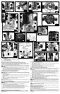
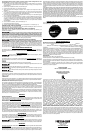
GRIPVAC™ PARTS (FIG. 12)
A. Router base B. Dust port
C. GripVac handle D. Removed handle and screw
E. Dust deflector F. Sub-base with screws
G. Hex screw (2) H. Shoulder washer
J. Hex nut
INSTALLING THE OPTIONAL GRIPVAC™ (FIXED BASE ONLY)
To reduce the risk of injury, turn unit off and disconnect it from power source before
installing and removing accessories, before adjusting or when making repairs. An accidental start-up
can cause injury.
1. Use a 5/16" hex wrench to loosen the screw in the handle (A) Fig. 14. Remove the handle from
the router base. Store the handle and screw for possible later use.
2. Remove the plastic plug from the dust port (B) Fig. 12.
3. Remove the screws (B) Fig. 15 and remove the sub-base (A) Fig. 15.
4. Align the holes of the GripVac™ handle to the holes of the router base.
5. Insert a hex screw (G) Fig. 12 through the handle into the hole (L). From inside the base housing,
place a shoulder washer (H) and a hex nut (J) on the screw. Tighten the nut loosely.
6. From inside the base housing, insert the second screw (G) into the hole (K) and screw it into the
threaded hole of the GripVac
™
handle.
7. Turn the router base upside down and place the dust deflector (E) Figs. 14 and 18 into the bottom
of the router base by aligning the three plastic tabs on the deflector with the three recesses in the
base. Align the extended part of the deflector (B) Fig. 16 with the GripVac
™
handle. The deflector
will be flush with bottom of router base.
8. Replace the sub-base and the three screws (Fig. 15).
9. Tighten all hardware securely.
10. Connect any vacuum/dust collection system with a 1" hose to the Grip Vac
™
handle Fig. 17.
SOFT START (ALL UNITS)
This router has a “Soft Start” feature designed to minimize startup reaction torque.
TEMPLATE GUIDES (NOT OFFERED FOR ALL MODELS)
A wide variety of template guides is available for use in pattern and templet routing operations.
To reduce the risk of injury, turn unit off and disconnect it from power source before
installing and removing accessories, before adjusting or when making repairs. An accidental start-
up can cause injury.
To install, insert the templet guide in the center hole of the router base and secure it in place with a
locknut. (See Fig. 13 for a guide.) Before connecting the router to the power source, install the
bit, adjust the depth of cut, and rotate the router chuck by hand to ensure that the bit or collet do
not contact the templet guide.
USING A ROUTER ACCESSORY TABLE (ALL UNITS)
To reduce the risk of injury, turn unit off and disconnect it from power source before
installing and removing accessories, before adjusting or when making repairs. An accidental start-
up can cause injury.
The router can be mounted to a router accessory table (not included). To open the clamp
for motor removal, use a hex wrench in the hole (C), Fig. 15. To adjust cutting depth, use a
hex wtrench in the hole (D) Fig. 15. For instructions on how to mount the router to the router
accessory table, refer to the accessory table instruction manual.
TROUBLESHOOTING
For assistance with your tool, visit our website at www.porter-cable.com for a list of service centers, or
call the Porter-Cable Customer Care Center at (888) 848-5175.
MAINTENANCE
To reduce the risk of injury, turn unit off and disconnect it from power source before
installing and removing accessories, before adjusting or when making repairs. An accidental start-up
can cause injury.
REPAIRS
For assistance with your tool, visit our website at www.porter-cable.com for a list of service centers, or
call the Porter-Cable Customer Care Center at (888) 848-5175.
CLEANING
Periodically blow out all air passages with dry compressed air.
Wear ANSI Z87.1 safety glasses while using compressed air.
Use only mild soap and a damp cloth to clean the tool.
Never let any liquid get inside the tool; never immerse any part of the tool into a liquid.
Never use solvents or other harsh chemicals for cleaning the non-metallic parts of the tool.
FAILURE TO START
Should your tool fail to start, check to make sure the prongs on the cord plug are making good contact
in the outlet. Also, check for blown fuses or open circuit breakers in the line.
LUBRICATION
This tool has been lubricated with a suffi cient amount of high grade lubricant for the life of the unit under
normal operating conditions. No further lubrication is necessary.
BRUSH INSPECTION (If applicable)
For your continued safety and electrical protection, brush inspection and replacement on this tool should
ONLY be performed by a PORTER-CABLE FACTORY SERVICE CENTER OR PORTER-CABLE AUTHO-
RIZED WARRANTY SERVICE CENTER.
At approximately 100 hours of use, take or send your tool to your nearest Porter-Cable Factory Service
center or Porter-Cable Authorized Warranty Service Center to be thoroughly cleaned and inspected.
Have worn parts replaced and lubricated with fresh lubricant. Have new brushes installed, and test the
tool for performance.
Any loss of power before the above maintenance check may indicate the need for immediate servicing
of your tool. DO NOT CONTINUE TO OPERATE TOOL UNDER THIS CONDITION. If proper operating
voltage is present, return your tool to the service station for immediate service.
SERVICE
REPLACEMENT PARTS
Use only identical replacement parts. For a parts list or to order parts, visit our website at servicenet.
porter-cable.com. You can also order parts from your nearest Porter-Cable Factory Service Center or
Porter-Cable Authorized Warranty Service Center. Or, you can call our Customer Care Center at (888)
848-5175.
SERVICE AND REPAIRS
All quality tools will eventually require servicing and/or replacement of parts. For information about Por-
ter-Cable, its factory service centers or authorized warranty service centers, visit our website at www.
porter-cable.com or call our Customer Care Center at (888) 848-5175. All repairs made by our service
centers are fully guaranteed against defective material and workmanship. We cannot guarantee repairs
made or attempted by others.
You can also write to us for information at PORTER-CABLE, 4825 Highway 45 North, Jackson, Tennes-
see 38305 - Attention: Product Service. Be sure to include all of the information shown on the nameplate
of your tool (model number, type, serial number, etc.).
ACCESSORIES
A complete line of accessories is available from your Porter-Cable Factory Service Center or a Porter-
Cable Authorized Warranty Service Center. Please visit our Web Site www.porter-cable.com for a cata-
log or for the name of your nearest supplier.
Since accessories other than those offered by Porter-Cable have not been tested with this
product, use of such accessories could be hazardous. For safest operation, only Porter-Cable recom-
mended accessories should be used with this product.
WARRANTY
To register your tool for warranty service visit our website at
www.porter-cable.com
.
PORTER-CABLE LIMITED ONE YEAR WARRANTY: Porter-Cable warrants its Professional Power Tools for a
period of one year from the date of original purchase. We will repair or replace at our option, any part or parts
of the product and accessories covered under this warranty which, after examination, proves to be defective
in workmanship or material during the warranty period. For repair or replacement return the complete tool or
accessory, transportation prepaid, to your nearest Porter-Cable Factory Service Center or Porter-Cable
Authorized Warranty Service Center. Proof of purchase may be required. This warranty does not apply to
repair or replacement required due to misuse, abuse, normal wear and tear or repairs attempted or made by
other than our servicecCenters or authorized warranty service centers.
ANY IMPLIED WARRANTY, INCLUDING THE IMPLIED WARRANTIES OF MERCHANTABILITY AND FIT-
NESS FOR A PARTICULAR PURPOSE, WILL LAST ONLY FOR ONE (1) YEAR FROM THE DATE OF PUR-
CHASE. To obtain information on warranty performance please write to: PORTER-CABLE, 4825 Highway 45
North, Jackson, Tennessee 38305; Attention: Product Service. THE FOREGOING OBLIGATION IS PORTER-
CABLE’S SOLE LIABILITY UNDER THIS OR ANY IMPLIED WARRANTY AND UNDER NO CIRCUMSTANC-
ES SHALL PORTER-CABLE BE LIABLE FOR ANY INCIDENTAL OR CONSEQUENTIAL DAMAGES. Some
states do not allow limitations on how long an implied warranty lasts or the exclusion or limitation of incidental
or consequential damages, so the above limitation or exclusion may not apply to you.
This warranty gives you specifi c legal rights and you may also have other legal rights which vary from state to
state.
WARNING LABEL REPLACEMENT
If your warning labels become illegible or are missing, call (888) 848-5175 for a free replacement.
t
s
u
d e
r
u
s
ek
a
M
yletelpmoc s
i
tro
p
nehw derevoc
.loot gnitarepo
ELBAC-
RE
T
R
OP
.A.
S
.U50
3
8
3
N
T
,
N
O
SKCAJ
OCIXEMNIEDAM
09
8
TNEMESSITREVA
,fitnevérPertiTÀ
.LAUNA
MNOIT
CURTSNID
N
ATSREDNU
KSIREHTECUDEROT
DNADAERTSUMRESU,YRUJNIFO
.ediug
ele
r
i
l
l
e
doM
re
tu
oRy
t
uDy
va
e
H
1EPYT
.
o
Nr
e
S