


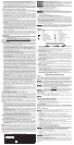

ENVIRONMENTAL SAFETY
1. Paint should be removed in such a manner as to minimize the amount of dust generated.
2. Areas where paint removal is occurring should be sealed with plastic sheeting of 4 mil thickness.
3. Sanding should be done in a manner to reduce tracking of paint dust outside the work area.
CLEANING AND DISPOSAL
1. All surfaces in the work area should be vacuumed and thoroughly cleaned daily for the duration
of the sanding project. Vacuum filter bags should be changed frequently.
2. Plastic drop cloths should be gathered up and disposed of along with any dust chips or other
removal debris. They should be placed in sealed refuse receptacles and disposed of through
regular trash pick-up procedures. During clean up, children and pregnant women should be kept
away from the immediate work area.
3. All toys, washable furniture and utensils used by children should be washed thoroughly before
being used again.
Save theSe inStructionS
MOTOR
Be sure your power supply agrees with nameplate marking. 120 Volts AC means your tool will operate on
alternating current. As little as 10% lower voltage can cause loss of power and can result in overheating.
All Porter Cable tools are factory-tested; if this tool does not operate, check the power supply.
Accessories must be rated for at least the speed recommended on the tool warning label.
Accessories running over rated speed can fly apart and cause injury. Accessory ratings must always be
above tool speed as shown on tool nameplate.
To reduce the risk of injury, turn unit off and disconnect it from power source
before installing and removing accessories, before adjusting or when making repairs. An
accidental start-up can cause injury.
OPERATION
To reduce the risk of injury, turn unit off and disconnect it from power source before
installing and removing accessories, before adjusting or when making repairs. An accidental start-
up can cause injury.
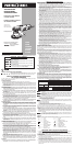
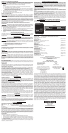
AUXILIARY HANDLE
An auxiliary handle (A) Fig. 1 is furnished with the tool. You can install the auxiliary handle on either
side of the front housing to facilitate either right-handed or left-handed operation.
Use this handle at all times to maintain complete control of the tool.
TO START AND STOP TOOL
Make certain that the switch is in the “OFF” position, and the power source is the same as that
specified on the tool’s nameplate.
1. Connect the tool to the power source.
2. Slide the switch button (B) Fig. 1 forward to start the motor. Slide the switch button to the rear
to stop the motor.
VARIABLE SPEED
Adjust the speed by turning the thumbwheel (C) Fig. 2. Thumb-wheel position #1 provides the slow-
est operating speed (2500 OPM) and position #6, the fastest (6800 OPM). You can change the speed
while the motor is running or while it is stopped.
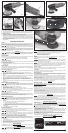
USING THE POLISHER (FIG. 3)
If your workpiece is so light that it can be moved by the rotating pad, anchor it securely
to prevent possible bodily injury.
1. Read and follow the directions supplied with the product (polishes, waxes, cleaners, etc.).
2. Apply a small amount of the product directly to the polishing pad.
3. Grasp the polisher firmly with both hands - one hand on auxiliary handle and one hand on motor
housing.
4. Position the polisher with the polishing pad against the work surface and start the polisher.
NEVER run or stop the tool when it is not in contact with the work surface.
5. Move the polisher back and forth in a sweeping motion, over-lapping each previous pass.
6. DO NOT apply additional pressure. Allow the polisher to work under its own weight.
7. Do not mix products (wax, polish, cleaner, etc.) on the same pad. Label each pad to prevent
confusion.
8. The polishing pad is designed for product application only. Remove product residue with a soft
cotton cloth.
INSTALLING/REMOVING ABRASIVE DISC (FIG. 4)
To reduce the risk of injury, turn unit off and disconnect it from power source before
installing and removing accessories, before adjusting or when making repairs. An accidental start-
up can cause injury.
1. Place the tool on the work-bench with the pad up (Fig. 4).
2. Clean dust from the pad face.
3. Position the disc on the sander pad and press the disc firmly on the pad.
4. Position the tool with the abrasive contacting scrap material. Start the tool and operate it
momentarily with firm pressure to seat the disc to the pad.
Failure to properly seat the disc to the pad may result in the disc being thrown from
the pad, causing personal injury.
6. Remove the disc by peeling it away from pad.
NOTE FOR PSA PADS:Donotstorethetoolwiththeabrasivediscinstalled.Heatgeneratedbythe
sanding operation increases the adhesive bond between the disc and the pad. If the disc is left on
the pad for an extended period of time after use, it will be difficult to remove.
CHANGING THE BACK-UP PAD
To reduce the risk of injury, turn unit off and disconnect it from power source before
installing and removing accessories, before adjusting or when making repairs. An accidental start-
up can cause injury.
1. Engage the flats of the spindle (D) Fig. 5 with the supplied spindle wrench (E).
NOTES:
A. If necessary, rotate the pad by hand to expose the spindle flats.
B. The pad is removed in Fig. 5 for clarity.
C. A spacer is supplied with the 7346SP and 7424XP to allow the backup pad to clear the eccen-
tric plate screws (F) Fig. 5. Mount the spacer on the shaft before attaching the backup pad.
2. While holding the spindle with the wrench, use your other hand to rotate the pad counterclock-
wise to remove.
3. To install the pad, reverse the above procedure.
USING THE SANDER (FIG. 6)
Secure the workpiece to prevent it from moving. Friction between the sanding disc and the work-
piece can spin the workpiece away from sander and may cause bodily injury.
Always use eye protection. To reduce the risk of injury, all users and bystanders must
wear eye protection that conforms to ANSI Z87.1.
Use of this tool can generate and/or disburse dust, which may cause serious and
permanent respiratory or otherinjury. Alwaysuse NIOSH/OSHA approved respiratoryprotection
appropriate for the dust exposure. Direct particles away from face and body.
INSTALLING ACCESSORY DUST COLLECTION ADAPTER AND HOSE
To reduce the risk of injury, turn unit off and disconnect it from power source before
installing and removing accessories, before adjusting or when making repairs. An accidental start-
up can cause injury.
1. Remove sander pad (G) Fig. 4.
2. LoosenPhillipsheadscrew(H)Fig.7ondustcollectionadapter(I)andslidetheadapteruponto
the vacuum housing (J) as shown in Fig. 7.
3. Orient dust hole (K) Fig. 8 as shown and tighten Phillips head screw.
4. Attach dust hose adapter (L) and dust hose (M) as shown.
TROUBLESHOOTING
For assistance with your tool, visit our website at www.deltaportercable.com for a list of service centers,
or call the PORTER-CABLE Customer Care Center at (888) 848-5175.
MAINTENANCE
To reduce the risk of injury, turn unit off and disconnect it from power source before
installing and removing accessories, before adjusting or when making repairs. An accidental start-
up can cause injury.
ALWAYS USE SAFETY GLASSES. Everyday eyeglasses are NOT safety glasses. Also use
face or dust mask if cutting operation is dusty. ALWAYS wear certified safety equipment:
• ANSIZ87.1eyeprotection(CAN/CSAZ94.3)
• ANSIS12.6(S3.19)hearingprotection
• NIOSH/OSHA/MSHArespiratoryprotection.
REPAIRS
For assistance with your tool, visit our website at www.deltaportercable.com for a list of service centers,
or call the PORTER-CABLE Customer Care Center at (888) 848-5175.
CLEANING
Periodically blowing dust and chips out of the motor housing using clean, dry compressed
air is a suggested maintenance procedure. To reduce the risk of serious personal injury, ALWAYS wear
ANSI Z87.1 safety glasses while using compressed air.
When cleaning, use only mild soap and a damp cloth on plastic parts. Many household
cleaners contain chemicals which could seriously damage plastic. Also, do not use gasoline, turpentine,
lacquer, paint thinner, dry cleaning fluids or similar products which may seriously damage plastic parts.
NEVER let any liquid get inside the tool; NEVER immerse any part of the tool into a liquid.
FAILURE TO START
Should your tool fail to start, check to make sure the prongs on the cord plug are making good contact in
the outlet. Also, check for blown fuses or open circuit breakers in the line.
LUBRICATION
This tool has been lubricated with a sufficient amount of high grade lubricant for the life of the unit under
normal operating conditions. No further lubrication is necessary.
BRUSH INSPECTION
For your continued safety and electrical protection, brush inspection and replacement on this tool
should ONLY be performed by a PORTER-CABLE FACTORY SERVICE CENTER OR PORTER-CABLE
AUTHORIZEDWARRANTYSERVICECENTER.
At approximately 100 hours of use, take or send your tool to your nearest PORTER-CABLE Factory
Service center or PORTER-CABLE Authorized Warranty Service Center to be thoroughly cleaned and
inspected.Havewornpartsreplacedandlubricatedwithfreshlubricant.Havenewbrushesinstalled,and
test the tool for performance.
Any loss of power before the above maintenance check may indicate the need for immediate servicing of
yourtool.DONOTCONTINUETOOPERATETOOLUNDERTHISCONDITION.Ifproperoperatingvoltage
is present, return your tool to the service station for immediate service.
SERVICE
REPLACEMENT PARTS
Use only identical replacement parts. For a parts list or to order parts, visit our service website at
www.deltaportercableservicenet.com. You can also order parts from your nearest PORTER-CABLE
Factory Service Center or PORTER-CABLE Authorized Warranty Service Center. Or, you can call our
Customer Care Center at (888) 848-5175.
SERVICE AND REPAIRS
All quality tools will eventually require servicing and/or replacement of parts. For information about
PORTER-CABLE, its factory service centers or authorized warranty service centers, visit our website at
www.deltaportercable.com or call our Customer Care Center at (888) 848-5175. All repairs made by our
service centers are fully guaranteed against defective material and workmanship. We cannot guarantee
repairs made or attempted by others.
YoucanalsowritetousforinformationatPORTER-CABLE,4825Highway45North,Jackson,Tennessee
38305 - Attention: Product Service. Be sure to include all of the information shown on the nameplate of
your tool (model number, type, serial number, etc.).
ACCESSORIES
Since accessories, other than those offered by PORTER-CABLE, have not been tested with
this product, use of such accessories with this tool could be hazardous. To reduce the risk of injury, only
PORTER-CABLE recommended accessories should be used with this product.
A complete line of accessories is available from your PORTER-CABLE Factory Service Center or a
PORTER-CABLE Authorized Warranty Service Center. Please visit our Web Site www.deltaportercable.
com for a catalog or for the name of your nearest supplier.
THREE YEAR LIMITED WARRANTY
PORTER-CABLE will repair, without charge, any defects due to faulty materials or workmanship for three
years from the date of purchase. This warranty does not cover part failure due to normal wear or tool
abuse. For further detail of warranty coverage and warranty repair information, visit www.deltaportercable.
com or call (888) 848-5175. This warranty does not apply to accessories or damage caused where repairs
have been made or attempted by others. This warranty gives you specific legal rights and you may have
other rights which vary in certain states or provinces.
In addition to the warranty, PORTER-CABLE tools are covered by our:
1 YEAR FREE SERVICE: PORTER-CABLE will maintain the tool and replace worn parts caused by nor-
mal use, for free, any time during the first year after purchase.
90 DAY MONEY BACK GUARANTEE: If you are not completely satisfied with the performance of your
PORTER-CABLE Power Tool, Laser, or Nailer for any reason, you can return it within 90 days from the date
of purchase with a receipt for a full refund – no questions asked.
LATIN AMERICA: This warranty does not apply to products sold in Latin America. For products sold in
Latin America, see country specific warranty information contained in the packaging, call the local com-
pany or see website for warranty information.
To register your tool for warranty service visit our website at www.deltaportercable.com.
WARNING LABEL REPLACEMENT
If your warning labels become illegible or are missing, call (888) 848-5175 for a free replacement.
TO REDUCE THE
RISK OF INJURY,
USER MUST READ INSTRUCTION MANUAL.
ALWAYS USE PROPER EYE AND RESPIRATORY
PROTECTION.
U. S. PATENT 5,061,090 D326042
PORTER-CABLE, JACKSON, TN 38305 U.S.A.
Model 7XXX
6" (152 mm) Variable Speed
Random Orbit Sander
PARA EL MANEJO
SEGURO LEA EL
MANUAL DE INSTRUCCIONES. SIEMPRE SE DEBERÁ
LLEVAR LA PROTECCIÓN APROPIADA PARA LA VISTA Y
PARA LAS VÍAS RESPIRATORIAS.
À TITRE PRÉVENTIF,
LIRE LE GUIDE. IL
FAUT TOUJOURS PORTER DE L’ÉQUIPEMENT DE
PROTECTION OCULAIRE ET RESPIRATOIRE APPROPRIÉ.
PARA EL MANEJO
SEGURO LEA EL
MANUAL DE INSTRUCCIONES. SIEMPRE SE DEBERÁ
LLEVAR LA PROTECCIÓN APROPIADA PARA LA VISTA Y
PARA LAS VÍAS RESPIRATORIAS.
À TITRE PRÉVENTIF,
LIRE LE GUIDE. IL
FAUT TOUJOURS PORTER DE L’ÉQUIPEMENT DE
PROTECTION OCULAIRE ET RESPIRATOIRE APPROPRIÉ.
FIG. 1
FIG. 2 FIG. 3
FIG. 4
FIG. 5 FIG. 6
FIG. 7
FIG. 8
A
C
B
J
D
E
F
L
M
K
G
I
H