


10 - ENGN020206
DRAIN
TRAP
DRAIN
TRAPS
DRAIN
LEGS
MOISTURE
SEPARATOR
AND TRAP
DIRT
LEG
DIRT
LEG
LUBRICATOR
REGULATOR
FILTER
AIR DISCHARGE
VALVE/ GLOBE VALV E
LUBRICATOR
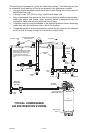
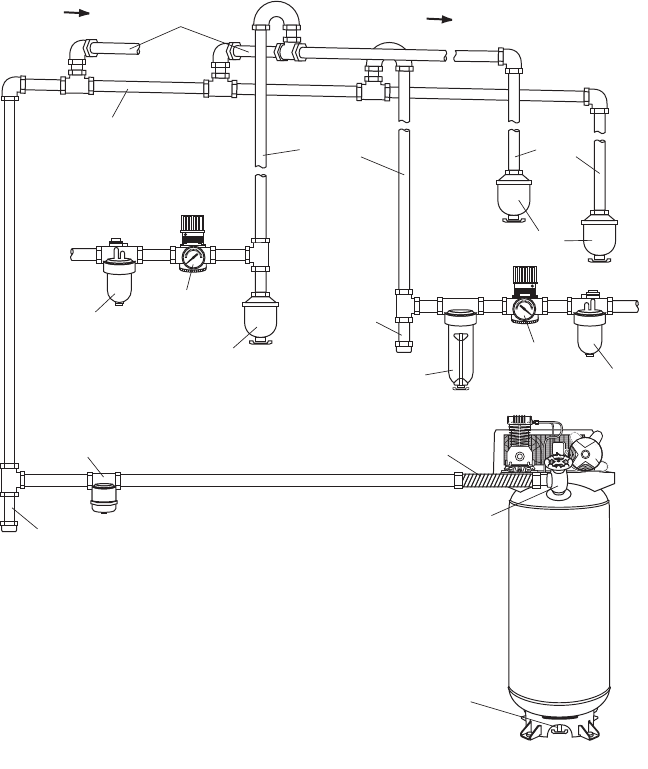
MAIN DISTRIBUTION AIR LINES
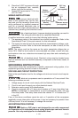
Slope pipe in direction of air flow.
Water condensate flows along
bottom of pipe to drain legs,
preventing it from entering feeder
lines.
REGULATOR
FLEXIBLE
COUPLING
DRAIN COCK
VALV E
TYPICAL COMPRESSED
AIR DISTRIBUTION SYSTEM
AIR FLOW
AIR FLOW
FEEDER LINES SLOPE
WITH AIR FLOW
AIR USAGE
LINES
AIR
COMPRESSOR
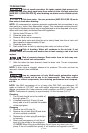
The next figure represents a typical air distribution system. The following are tips
to remember when setting up the air compressor’s air distribution system.
• Usepipethatisthesamesizeastheairtankoutlet.Pipingthatistoosmallwill
restrict the flow of air.
• Ifpipingisover100'(30.5m)long,usethenextlargersize.
• Buryundergroundlinesbelowthefrostlineandavoidpocketswhereconden-
sation can gather and freeze. Apply pressure before underground lines are
covered to make sure all pipe joints are free of leaks.
• Aflexiblecouplingisrecommendedtobeinstalledbetweentheairdischarge
outlet and main air distribution line to allow for vibration.
• Aseparateregulatorisrecommendedtocontroltheairpressure.Airpressure
from the tank is usually to high for individual air driven tools.