


SAVE THESE INSTRUCTIONS!
MOTOR
Do not operate your tool on a current on which the voltage is not within correct limits. Do
not operate tools rated A.C. only on D.C. current. To do so may seriously damage the tool.
ASSEMBLY
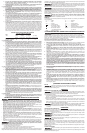
REPLACING THE SANDING BELT
To reduce the risk of injury, be sure sander is turned off and disconnected from the power
supply when changing the sanding belt. Before reconnecting the tool, make sure the switch (D) Fig. 2 is
in the off position.
To replace the belt:
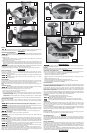
1. Rotate the belt release lever (A) Fig. 1 up until front wheel of the sander (B) Fig. 1 retracts and
releases the tension on the abrasive belt (C).
2. Remove the worn out belt.
3. Slip a new belt around the wheels. Sanding belts without arrows can go either direction. If the
belt is unidirectional and has arrows printed on its inside, make sure to point these arrows in the
direction of wheel rotation.
(Wheel rotation would be clockwise when looking into the open side of
the sander)
.
Severe laceration hazard. If installed backwards, unidirectional sanding belts may not track
properly and may overhang the housing, possibly causing severe lacerations.
4. Rotate the belt release lever (A) Fig. 1 down into position to reapply tension to the belt.
OPERATION
SWITCH OPERATION
To turn unit on, depress the side of the dust-protected switch (D) Fig. 2 that reads “ON” and cor-
responds to the symbol “I.” To turn the unit off, depress the side of the switch that reads “OFF” and
corresponds with the symbol “O.”
To reduce the risk of injury, make sure the sander is not resting on the workpiece when
the switch is turned on.
To reduce the risk of injury, check to see that the belt guard (T) Fig. 1 is in place,
secured, and working correctly.
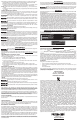
FRONT HANDLE
The front auxilliary handle is removeable to allow the sander into tight spaces. The unit comes with
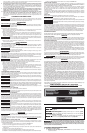
the handle (E) Fig. 2 installed as shown. To remove the handle, loosen the screw (S) Fig. 4 in the
center of the handle using a flat head screwdriver and then remove handle and screw.
NOTE: The handle must be properly seated over the mounting surface before tightening the
screw.
TRACKING THE BELT
Severe laceration hazard. Properly adjust the tracking of the belt to avoid it overhanging
the housing. A running belt overhanging the housing can cause severe lacerations.
Make sure the sanding belt is tracking properly on your unit. To do this:
1. Grasp unit in your hand and hold with the belt facing you.
2. Turn on switch (D) Fig. 2 to start the belt.
3. Turn the tracking knob (G) Fig. 3 counterclockwise (turning towards the front of the sander) to
move the belt toward the housing. Turn the knob clockwise (towards the power cord) to move
it away from the housing.
NOTE: The belt should be aligned with the flush edge of the platen (H) Fig. 1 while the sander
is in operation.
4. Turn switch off and make sure the belt has come to a complete stop before setting unit down.
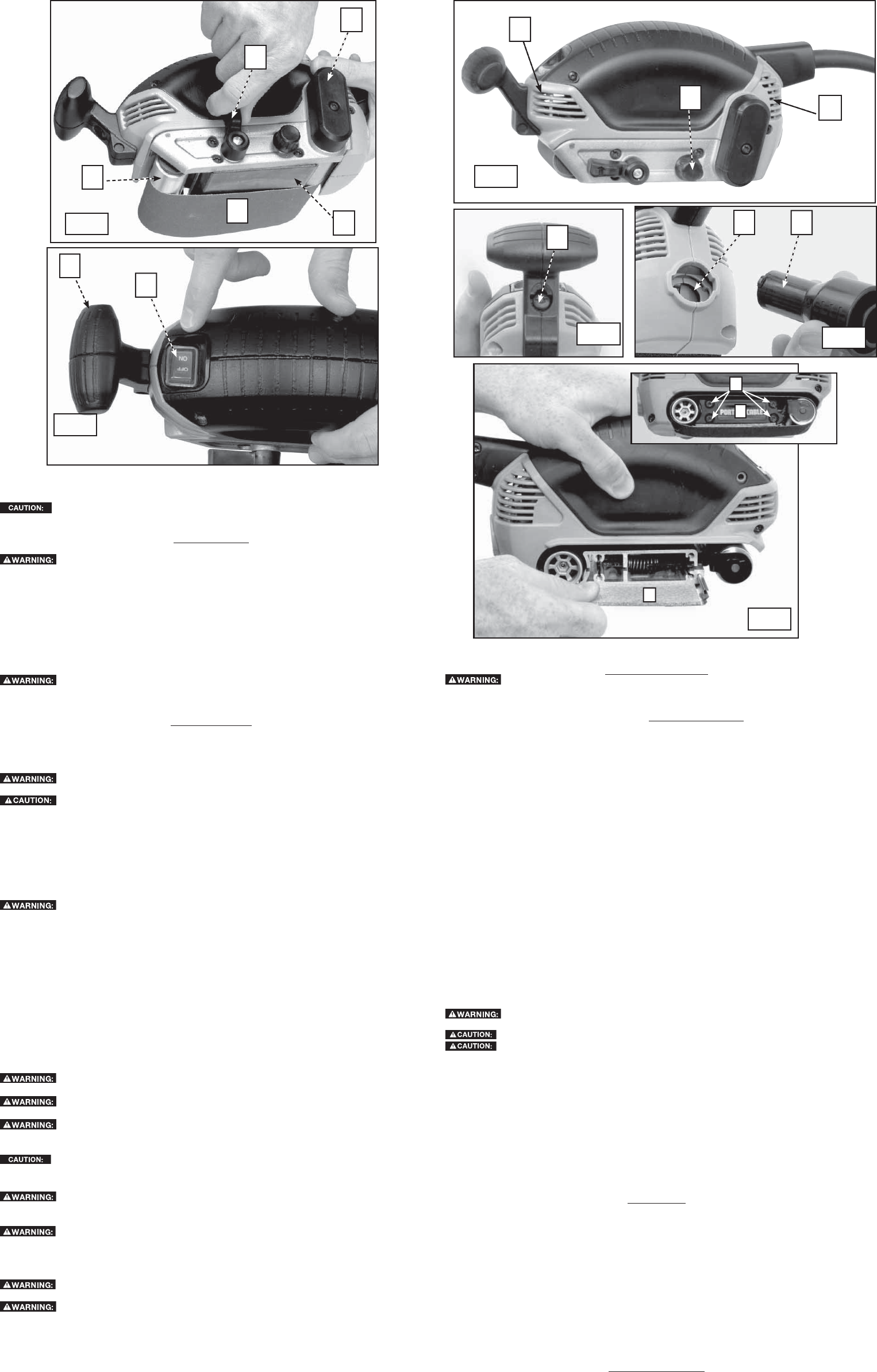
PROPER HAND POSITION
This can be a one-handed tool. Proper hand position would be to have one hand on the rubber
portion of the body, as shown in Fig. 6. If needed, the other hand can grip the auxilliary handle (E)
Fig. 2.
Severe abrasion hazard. Keep hands and fingers clear of moving sanding belt. Failure to
do so could result in the sanding of the hands or fingers possibly causing serious injury.
Severe pinching hazard. Keep hands and fingers clear of front roller at all times. Failure to
do so could result in fingers getting pinched, causing possible serious injury.
Severe abrasion hazard. Do not let the fingers rest over the front or right edge of the sander.
If the sanding belt were to run off, or if it were not properly adjusted, your fingers could come in contact
with the moving sanding belt resulting in possible serious injury.
Make sure all air vents on the sander (L) and (M) Fig. 3 are not covered during use.
OPERATING THE SANDER
Before sanding a workpiece, make sure it is secured or clamped down.
To reduce the risk of injury, always secure work to prevent it from being thrown back
towards the user.
VACUUM ADAPTER
Empty dust collection system frequently, especially when sanding resin-coated sur-
faces such as polyurethane, varnish, shellac, etc. Dispose of coated dust particles according to
the fi nish manufacturer’s guidelines, or place in a metal can with a tight fi tting metal lid. Remove
coated dust particles from the premises daily. The accumulation of fi ne sanding dust particles may
self ignite and cause fi re.
Shock hazard. The use of a vacuum hose and vacuum adapter with the belt sander
may generate static electricity that could result in startling static discharge.
Do not use a dust collection device when sanding metal. Doing so creates a fire hazard,
which may cause serious personal injury and/or damage to the tool.
Your belt sander is equipped with a dual hose adpater. The adapter can be attached to both 1"
(inside diameter) and 35 mm (outside diameter) shop vacuum hoses for dust collection. Insert the
adpater (J) Fig. 5 into the dust port (K) and turn it 1/8 turn clockwise to secure the adapter to the
sander. Then, attach the appropriate vacuum hose to the adapter.
MAINTENANCE
To reduce the risk of injury, turn off and unplug sander before making any adjustments
or removing or installing accessories.
REPAIRS
For assistance with your tool, visit our website at www.porter-cable.com for a list of service centers, or
call the Porter-Cable Customer Care Center at (888) 848-5175.
TO REPLACE THE PLATEN/CORK
The cork under the platen on your belt sander may require replacement at some point during the life
of the tool. A new platen/cork is available through your PORTER-CABLE service center.
1. Remove the sanding belt as described in ASSEMBLY.
2. Rotate the belt release lever (A) Fig. 1 down.
3. Remove the plastic cover (N) Fig. 6 (inset) from right side of platen by removing four screws
(O).
4. Slide old platen/cork (P) Fig. 6 out.
5. Slide the new platen/cork into the sander and discard the old one.
6. Reinstall the plastic cover and make sure the tracking spring is installed correctly.
7. Install a sanding belt as described in ASSEMBLY.
BRUSH INSPECTION
For your continued safety and electrical protection, brush inspection and replacement on this tool
should ONLY be performed by a PORTER-CABLE FACTORY SERVICE CENTER OR PORTER-CABLE
AUTHORIZED WARRANTY SERVICE CENTER.
At approximately 100 hours of use, take or send your tool to your nearest Porter-Cable Factory
Service center or Porter-Cable Authorized Warranty Service Center to be thoroughly cleaned and
inspected. Have worn parts replaced and lubricated with fresh lubricant. Have new brushes installed,
and test the tool for performance.
Any loss of power before the above maintenance check may indicate the need for immediate servicing
of your tool. DO NOT CONTINUE TO OPERATE TOOL UNDER THIS CONDITION. If proper operating
voltage is present, return your tool to the service station for immediate service.
CLEANING
Periodically blow out all air passages with dry compressed air.
Wear ANSI Z87.1 safety glasses while using compressed air.
Use only mild soap and a damp cloth to clean the tool.
Never let any liquid get inside the tool; never immerse any part of the tool into a liquid.
Never use solvents or other harsh chemicals for cleaning the non-metallic parts of the tool.
LUBRICATION
This tool has been lubricated with a sufficient amount of high grade lubricant for the life of the unit
under normal operating conditions. No further lubrication is necessary. However, it is recommended
that, once a year, you take or send the tool to a PORTER-CABLE service center for a thorough
cleaning and inspection.
Any loss of power before the above maintenance check may indicate the need for immediate servicing
of your tool. DO NOT CONTINUE TO OPERATE TOOL UNDER THIS CONDITION. If proper operating
voltage is present, return your tool to the service station for immediate service.
FAILURE TO START
Should your tool fail to start, check to make sure the prongs on the cord plug are making good contact
in the outlet. Also, check for blown fuses or open circuit breakers in the line.
SERVICE
REPLACEMENT PARTS
Use only identical replacement parts. For a parts list or to order parts, please visit our website at
servicenet.porter-cable.com. You can also order parts from your nearest Porter-Cable Factory Service
Center or Porter-Cable Authorized Warranty Service Center. Or, you can call our Customer Care Center
at (888) 848-5175.
SERVICE AND REPAIRS
All quality tools will eventually require servicing and/or replacement of parts. For information about
Porter-Cable, its factory service centers or authorized warranty service centers, visit our website at
www.porter-cable.com or call our Customer Care Center at (888) 848-5175. All repairs made by our
service centers are fully guaranteed against defective material and workmanship. We cannot guarantee
repairs made or attempted by others.
You can also write to us for information at PORTER-CABLE, 4825 Highway 45 North, Jackson,
Tennessee 38305 - Attention: Product Service. Be sure to include all of the information shown on the
nameplate of your tool (model number, type, serial number, etc.).
ACCESSORIES
Fig. 1
Fig. 2
Fig. 3
Fig. 4
B
G
A
D
H
E
Fig. 5
C
M
L
S
JK
N
O
Fig. 6
P
T