


7-ENG
DESCRIPTION OF OPERATION
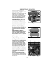
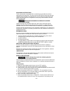
Compressor Pump (A) Fig. 1: To
compress air, the piston moves up and
down in the cylinder. On the
downstroke, air is drawn in through the
intake valves. The exhaust valves
remain closed. On the upstroke of the
piston, air is compressed. The intake
valves close and compressed air is
forced out through the exhaust valves.
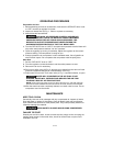
Check Valve (B) Fig. 2: When the air
compressor is operating, the check
valve is “open”, allowing compressed
air to enter the air tank. When the air
compressor reaches “cut-out” pressure,
the check valve “closes”, allowing air
pressure to remain inside the air tank.
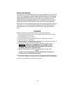
ON/AUTO - OFF Switch (C) Fig. 3:
Turn this switch ON to provide power to
the automatic pressure switch and OFF
to remove power at the end of each
use.
Pressure Switch (D) Fig. 3: The
pressure switch automatically starts the
motor when the tank pressure drops
below the factory set “cut-in” pressure.
It stops the motor when the air tank
pressure reaches the factory set “cut-
out” pressure.
Regulator (E) Fig. 1: The air pressure
coming from the air tank is controlled
by the regulator. Turn the regulator knob
clockwise to increase pressure and
counterclockwise to decrease pressure.
To avoid minor readjustment after
making a change in pressure setting,
always approach the desired pressure
from a lower pressure. When reducing
from a higher to a lower setting, first
reduce to pressure less than that
desired, then bring it up to the desired
pressure. Depending on the air require-
ments of each particular accessory, the
outlet regulated air pressure may have
to be adjusted while operating the
accessory.
Quick Connect Air Outlets (J) Fig. 1:
For easy connecting and disconnecting
of tools. Allows two tools to be used at
the same time.
B
E
F
A
Figure 1
Figure 2
L
Figure 3
G
K
C
D
H
J