


8-ENG
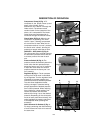
Outlet Pressure Gauge (F) Fig. 1: The outlet pressure gauge indicates the air
pressure available at the outlet side of the regulator. This pressure is controlled by
the regulator and is always less than or equal to the tank pressure. See “Operating
Procedures”.
Tank Pressure Gauge (G) Fig. 3: The tank pressure gauge indicates the reserve air
pressure in the tank.
Cooling System: This compressor contains an advanced design cooling system. At
the heart of this cooling system is an engineered fan. It is perfectly normal for this
fan to blow air through the vent holes in large amounts. You know that the cooling
system is working when air is being expelled.
Air Intake Filter (H) Fig. 3: This filter is designed to clean air flowing into the pump.
This filter must always be clean and free from obstructions. Twist filter cover
counter-clockwise to remove and expose paper filter element.
Drain Valve (L) Fig. 2: The drain valve is located at the base of the lower air tank
and is used to drain condensation at the end of each use.
Motor Thermal Overload Protector: The electric motor has an automatic thermal
overload protector. If the motor overheats for any reason, the thermal overload
protector will shut off the motor. The motor must be allowed to cool before
restarting.
Pressure Release Valve (not shown): The pressure release valve located on the
side of the pressure switch, is designed to automatically release compressed air
from the compressor head and the outlet tube when the air compressor reaches
“cut-out” pressure or is shut off. The pressure release valve allows the motor to
restart freely.
When the motor stops running, air will be heard escaping from this
valve for a few seconds. No air should be heard leaking when the motor is running,
or continuous leaking after unit reaches cut-out pressure.
Safety Valve (K) Fig. 3: If the pressure switch does not shut off the air compressor
at its cutout pressure setting, the safety valve will protect against high pressure by
“popping out” at its factory set pressure (slightly higher than the pressure switch
cut-out setting).
If the safety valve does not work properly, over-pressuri-
zation may occur, causing air tank rupture or an explosion. Daily pull
the ring on the safety valve to make sure that the safety valve
operates freely. If the valve is stuck or does not operate smoothly, it
must be replaced with the same type of valve.
INSTALLATION AND BREAK-IN PROCEDURES
LOCATION OF THE AIR COMPRESSOR
Your compressor comes to you completely assembled and ready for use. Operate
the air compressor in a dry, clean, cool and well ventilated area. The air compressor
pump and case are designed to allow for proper cooling. Clean or blow off dust or
dirt that collects on the air compressor. A clean air compressor runs cooler and
provides longer service. The ventilation openings on your air compressor are
necessary to maintain proper operating temperature. Do not place rags or other
containers on or near these openings.
VOLTAGE AND CIRCUIT PROTECTION
See SPECIFICATIONS Section of this manual.