


9
USING THE TOOL WITH DIFFERENT TRIGGERING OPTIONS
Complete all steps of PREPARING THE TOOL before using the tool.
This tool is shipped from the factory with a “single sequential actuation”
trigger which will limit the tool to firing method number 1 only.
A “contact actuation” trigger is available. The “contact actuation” trigger
allows the tool to be fired in either of two methods described below;
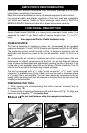
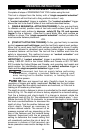
1. [SINGLE SEQUENTIAL ACTUATION TRIGGER]: To fire, grip tool firmly
to maintain control, position nose of tool onto work surface, push the tool
firmly against work surface to depress safety (S) Fig. 23, and squeeze
trigger to fire a fastener. Allow tool to recoil away from work surface as
fastener is driven. This “single sequential actuation” method provides the
most accurate fastener placement.
-OR-
2. [CONTACT ACTUATION TRIGGER]: To fire, grip tool firmly to maintain
control, squeeze and hold trigger, push the tool firmly against work surface.
Allow tool to recoil away from work surface as fastener is driven. If safety
element is allowed to recontact work surface before trigger is released an
unwanted fastener will be fired. The tool will fire a fastener each time the
safety is depressed. This method is known as “contact actuation” and
allows very fast repetitive fastener placement.
IMPORTANT: A“contact actuation” trigger is available free-of-charge by
calling 1-800-321-9443 in the United States and Canada or 001-731-660-
9374 outside the United States and Canada, and providing tool model and
serial number. For identification purposes: the contact actuation trigger is
black and the single sequential actuation trigger is red.
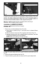
Disconnect tool from air supply before performing
maintenance, clearing a jammed fastener, leaving work
area, moving tool to another location, or handing the tool
to another person.
Clean and inspect tool daily. Carefully check for proper
operation of trigger and safety mechanism. Do Not use the tool unless
both the trigger and the safety mechanism are functional, or if the tool is
leaking air or needs any other repair.
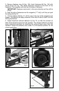
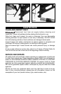
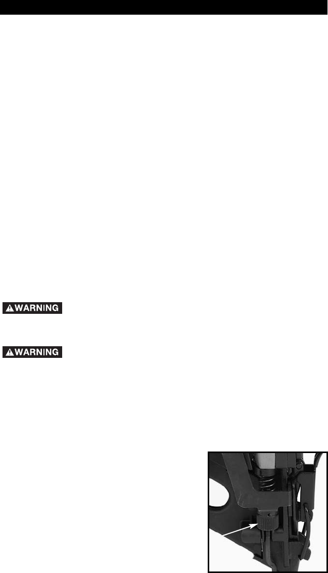
The depth to which a fastener is driven is controlled by the depth adjustment
knob (A) Fig. 24. The depth of drive is factory adjusted to a nominal setting.
Test fire a fastener and check depth. If a change is desired, rotate the
adjustment knob (A) Fig. 24. The adjustment knob has detents every
1
/4 turn.
Rotate the knob (A) Fig. 24 clockwise to increase the depth of drive, rotate
the knob counterclockwise to decrease the
depth of drive. Test fire another fastener and
check depth. Repeat as necessary to
achieve desired results. The amount of air
pressure required will vary depending on the
size of the fastener and the material being
fastened. Experiment with the air pressure
setting to determine the lowest setting that
will consistently perform the job at hand. Air
pressure in excess of that required can
cause premature wear and/or damage to the
tool.
OPERATING INSTRUCTIONS
Fig. 24
A