4- ENG
D25800
Prior to shipment, this gun was treated with an
anticorrosive agent. Before using this gun make sure that it is
carefully flushed with thinner.
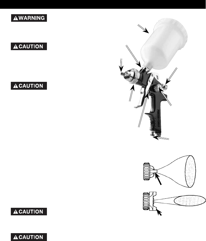
1. The po si tion of the air cap (H) horns will de ter mine the
spray pattern. Loosen (G) air cap and rotate horns to
achieve desired pattern. Tighten air cap.
2. Attach ma te ri al cup to the gun. NOTE: The (F) material filter
supplied is optional to protect against contaminants and
small particles. See parts list for material filter orientation.
3. Attach air supply line to 1/4 NPS air inlet.
NEVER point spray gun at self or any
oth er per son. Ac ci den tal discharge of
material may re sult in se ri ous injury.
4. Adjust air pres sure at air com pres sor.
DO NOT exceed 100 psi.
5. Depress spray gun trigger fully to spray ma te ri al. NOTE: Depressing trig ger partially will
cause only air to be re leased.
Adjust spray gun:
a. Amount of ma te ri al re leased (den si ty of “fan spray”) is con trolled by (D) fluid con trol knob.
Turn knob coun ter clock wise to in crease, or clock wise to de crease, the flu id flow.
b. Width of “fan spray” is gov erned by (B) pattern adjustment knob. Turn knob coun ter clock-
wise to in crease, or clock wise to de crease, air flow.
c. Air quan ti ty is con trolled by (C) air-volume con trol knob. Turn knob coun ter clock wise to
in crease, or clock wise to de crease, the air flow.
NOTE: Care should be ex er cised when handling spray gun to avoid dam age to the orifice of
the air cap and tip of fluid noz zle. Dam age to these parts results in ir reg u lar spray pat terns.
DO NOT ATTEMPT
TO UN CLOG (BACK
FLUSH) SPRAY GUN BY SQUEEZ ING
TRIG GER WHILE HOLD ING FIN GER IN
FRONT OF FLUID NOZZLE.
Pressure may vary
ac cord ing to viscosity
of material used. Max i mum working
pres sure of gun is 100 psi. DO NOT
EX CEED PRESSURE LIMIT OF GUN
OR ANY OTH ER COM PO NENT IN
SYSTEM!
Prior to daily
operation, make
certain that all connections and fit tings
are se cure. Check hose and all con-
nec tions for a weak or worn condition
that could render sys tem unsafe. All
re place ment com po nents such as
hose or fit tings must have a work ing
pressure equal to or great er than
system pres sure.
(A) Air
Valve Nut
(E) Non-Drip Cup
(G) Air Cap
(C) Air
Volume
Control Knob
(D) Fluid
Control
Knob
(B) Spray
Pattern
Adjustment
(H) Horns
Horizontal position
Vertical position
OPERATION
(F) Material
Filter


