


11
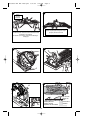
SUPPORTING LARGE PANELS / SECURING WORKPIECE
Support large panels to minimize the risk of blade pinching and kickback. Large panels
tend to sag under their own weight as shown in figure B. Supports must be placed
under the panel on both sides, near the line of cut and near the edge of the panel
(figure C).
Never hold piece being cut in your hands or across your leg (figure D). Secure the
workpiece to a stable platform as shown in figure E. It is important to support the work
properly to minimize body exposure, blade binding, or loss of control.
ASSEMBLY/ SET-UP
Always unplug saw from power supply before any of the following
operations.
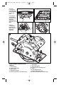
ADJUSTING THE DEPTH OF CUT (FIGURE F & G)
The depth of cut should be set according to the thickness of the workpiece.
• Loosen the lever (12) to unlock the saw shoe (figure F).
• Move the saw shoe (6) into the desired position. The corresponding depth of cut can
be read from the scale (13).
• Tighten the lever to lock the saw shoe in place.
• Set depth adjustment of saw such that one tooth of the blade projects below the
workpiece as shown in figure G. Setting the saw at the proper cutting depth keeps
blade friction to a minimum, removes sawdust from between the blade teeth, results in
cooler, faster sawing and reduces the chance of kickback.
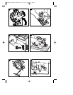
ADJUSTING THE BEVEL ANGLE (FIGURE H)
This tool can be set to bevel angles between 0° and 45°.
• Loosen the locking knob (14) to unlock the saw shoe.
• Move the saw shoe (6) into the desired position. The corresponding bevel angle can
be read from the scale (15).
• Tighten the locking knob to lock the saw shoe in place.
ATTACHING AND REMOVING THE BLADE
REMOVING THE BLADE (PC15CSL) (FIGURE I & J)
• Keep the spindle lock button (5) depressed and rotate the blade until the spindle lock
engages.
• Loosen and remove the blade retaining screw (16) by turning it counterclockwise
using the wrench (10) supplied.
• Remove the outer washer (17).
• Remove the saw blade (7).
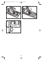
ATTACHING THE BLADE (PC15CSL)
• Place the saw blade (7), on the spindle shaft, making sure that the arrow on the
blade points in the same direction as the arrow on the tool.
• Fit the outer washer (17) on the spindle, with the raised part pointing away from the
saw blade.
• Insert the blade retaining screw (16) into the hole.
• Keep the spindle lock button (5) depressed.
• Securely tighten the blade retaining screw by turning it clockwise using the wrench
(10) supplied.
NOTE: The inner flange (18), should not be removed. If it is removed, replace it
as shown in figure J.
REMOVING THE BLADE (PC13CSL) (FIGURE K & J)
• Prevent spindle rotation by engaging the teeth of the saw blade into a piece of scrap
wood.
• Loosen and remove the blade retaining screw (16) by turning it counterclockwise
using the wrench (10) supplied.
• Remove the outer washer (17).
• Remove the saw blade (7).
:
90539190 REV MAY 2009.qxd 5/27/09 9:22 AM Page 11