


12
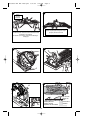
ATTACHING THE BLADE (PC13CSL)
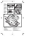
• Place the saw blade (7), on the spindle shaft, making sure that the arrow on the blade
points in the same direction as the arrow on the tool.
• Fit the outer washer (17) on the spindle, with the raised part pointing away from the
saw blade.
• Insert the blade retaining screw (16) into the hole.
• Prevent spindle rotation by engaging the teeth of the saw blade into a piece of scrap
wood.
• Securely tighten the blade retaining screw by turning it clockwise using the wrench
(10) supplied.
NOTE: The inner flange (18), should not be removed. If it is removed, replace it
as shown in figure J.
To reduce the risk of serious personal injury, read, understand and follow
all important safety warnings and instructions prior to using tool.
GENERAL CUTS (IMPORTANT: READ SAFETY WARNINGS AND INSTRUCTIONS. )
GUARD AGAINST KICKBACK
With unit unplugged, follow all assembly, adjustment and set up instructions.
Make sure lower guard operates. Select the proper blade for the material to be cut.
• Measure and mark work for cutting.
• Support and secure work properly (See Safety Rules and Instructions).
• Use appropriate and required safety equipment (See Safety Rules).
• Secure and maintain work area (See Safety Rules).
• With plug inserted and guard closed, make sure switch turns saw on and off.
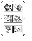
It is important to support the work properly and to hold the saw firmly to
prevent loss of control which could cause personal injury. Figure E illustrates
recommended hand position.
ATTACHING AND REMOVING THE RIP FENCE (INCLUDED WITH PC15CSL) FIG. L)
The rip fence is used to saw in a straight line parallel to the edge of the workpiece.
ATTACHING
• Loosen the locking knob (19).
• Insert the rip fence (20) through the openings (21).
• Slide the rip fence into the desired position.
• Tighten the locking knob.
REMOVING
• Loosen the locking knob.
• Pull the rip fence out of the tool.
NOTE: If you do not have a proper fitting fence, use a straight edge guide in contact with the
edge of the shoe to improve accuracy of cut and reduce the possibility of binding and
kickback.
OPERATION
SWITCH
• To operate the tool, depress the trigger switch (1). The tool will continue to run as long
as the trigger is depressed.
• To turn the tool off, release the trigger switch (1). There is no provision for locking the
tool on, and the switch should never be locked on by any other means.
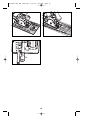
KERF PLATE ADJUSTMENT (FIGURE M)
The tool is equipped with a sight guide for straight cutting (22) and for 45° miter cutting
(23).
• Be sure the saw is unplugged.
• Adjust the kerf plate as described below.
• Align the left edge of the guides (22) or (23) with the cutting line.
:
:
90539190 REV MAY 2009.qxd 5/27/09 9:22 AM Page 12