


Page 7
5 32
9 64
1 8
7 64
3
3
3 16
13
64
11 64
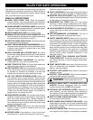
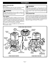
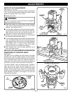
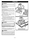
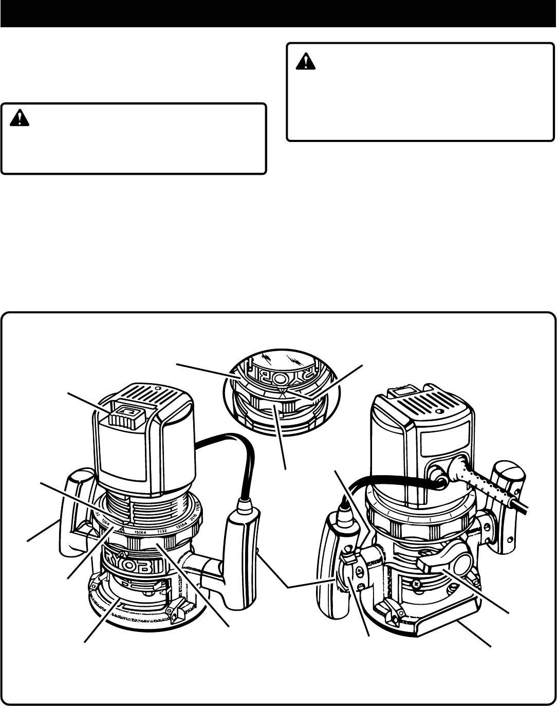
KNOW YOUR ROUTER
See Figure 1.
Before attempting to use your router, familiarize yourself
with all operating features and safety requirements.
CHIP SHIELD
A clear plastic chip shield is installed on the front of your
router for protection against flying dust and chips. The shield
is designed to fit the front opening of the router base.
See
Figure 1.
If necessary to remove chip shield, squeeze the
tabs on each end and pull outward. To replace, squeeze the
tabs at each end, fit into opening, then release.
Note: For your protection, do not use router without chip
shield properly in place.
WARNING:
Always wear safety goggles or safety glasses with side
shields when operating your router. Failure to do so could
result in dust, shavings, loose particles or foreign objects
being thrown into your eyes, causing possible serious
injury.
FEATURES
LOCK-ON BUTTON
The switch of your router is equipped with a "lock-on" feature
which is convenient when operating for extended periods of
time. To lock on, depress the trigger, push in the lock button
located on the side of the handle, then while holding the lock
button pushed in, release the trigger. To release the lock,
depress the trigger and release it.
See Figure 1.
WARNING:
Do not allow familiarity with your router to make you
careless. Remember that a careless fraction of a second
is sufficient to inflict severe injury.
3/
8
15
64
1
64
0
1
32
3
7
32
64
DEPTH
INDICATOR
RING(S)
Fig. 1
LOCK-ON
BUTTON
SWITCH
TRIGGER
SUBBASE WITH
STRAIGHT EDGE
CLAMPING
LEVER
INDICATOR
POINT(S)
POWER
HANDLE
FRONT VIEW OF ROUTER
REAR VIEW OF ROUTER
DEPTH
ADJUSTING
RING
UPSIDE DOWN VIEW OF ROUTER
SPINDLE
LOCK
CHIP
SHIELD
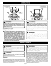
DEPTH
INDICATOR
RING(S)
DEPTH
ADJUSTING RING
HANDLE
INDICATOR
POINT(S)