


Page 9
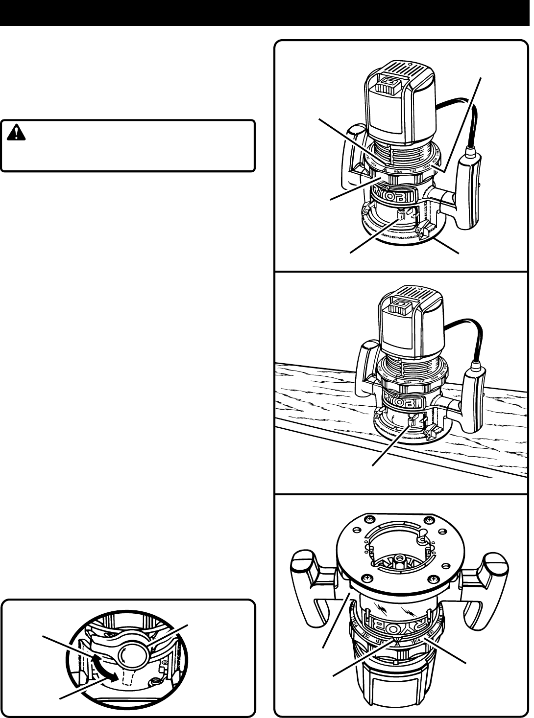
TO
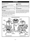
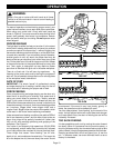
LOCK
CLAMPING
LEVER
Fig. 5
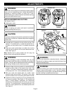
DEPTH
ADJUSTING
RING
SUBBASE
INDICATOR
POINT
CUTTER
INSIDE SUBBASE
DEPTH
INDICATOR
RING
CUTTER AT
ZERO DEPTH OF CUT
BASE
INDICATOR
POINT
DEPTH
INDICATOR
RING
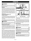
Fig. 7
FOR ROUTER TABLE USE ONLY
DEPTH OF CUT ADJUSTMENTS
See Figures 4, 5, 6, and 7.
We recommend that cuts be made at a depth not exceeding
1/8 in. (3 mm) and that several passes be made to reach
depths of cut greater than 1/8 in. (3 mm).
■ Unplug your router.
WARNING:
Failure to unplug your router could result in accidental
starting causing serious injury.
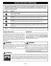
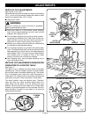
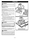
■ Place your router on a flat surface, unlock clamping
lever, and turn depth adjusting ring until cutter is inside
subbase.
See Figures 4 and 5.
■ Turn the depth adjusting ring until tip of cutter touches
flat surface (zero depth of cut).
See Figure 6.
Next turn
depth indicator ring until the zero lines up with the indi-
cator point on front of motor housing.
See Figure 5.
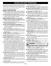
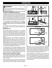
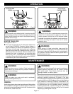
■ Position your router so that the cutter can extend below
the subbase for desired depth setting.
■ Turn the depth adjusting ring to obtain the desired depth
of cut. The distance the cutter moves can be read on the
depth adjusting ring. Each mark on the depth adjusting
ring indicates 1/64 in. (0.4 mm) change in depth setting.
One indicator point is located on front of the motor
housing, the other one is located on the base.
■ Lock clamping lever, securing depth adjusting ring to
motor housing and base.
DEPTH OF CUT ADJUSTMENTS WHEN ROUTER
IS MOUNTED TO A ROUTER TABLE
See Figure 7.
The depth of cut is readable from both sides of the depth
adjusting ring. There is a depth indicator ring and indicator
point on both sides of the depth adjusting ring. The bottom
ring is convenient when using your router mounted to a
router table. The indicator point on the base should also be
used when using your router mounted to a router table.
The depth indicator rings are identical parts. Therefore,
when you have your router mounted upside down on a
router table, you set depth of cut by reading the scale
different. Set the cutter at zero depth of cut, rotate depth
indicator ring to desired depth of cut on the scale, then turn
depth adjusting ring back to zero depth of cut and lock
clamping lever securely.
ADJUSTMENTS
Fig. 6
L
O
C
K
U
N
L
O
C
K
Fig. 4
TO
UNLOCK