


LX2206 EVALUATION BOARD USER GUIDE
Microsemi
Integrated Products
11861 Western Avenue, Garden Grove, CA. 92841, 714-898-8121, Fax: 714-893-2570
Page 6
Copyright © 2002
Rev. 1.1, 2006-11-17
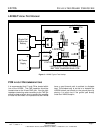
LX2206 EVAL CONNECTIONS
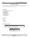
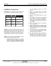
Connections: The LX2206 Evaluation Board has
one power input and one power output connection.
FUNCTION PIN NAME
VOLTAGE
Input Power PWR 5V +/- 0.65V
Input RTN GND 0V
Battery + BAT+ 0V to 4.3V
Battery - RTN 0V
Jumpers: The LX2206 Evaluation Board has two
position jumper blocks. The jumper can be moved to
select either a high logic level or low logic level. It is
also possible to remove the jumper and apply a
voltage directly to the center pin of the jumper block.
Hookup: The following is a demonstration scenario
that can be used to evaluate the LX2206.
1) Apply the single cell Lithium Ion or Lithium
polymer battery to the battery screw terminal
block. Be sure to connect the positive
terminal of the battery to the BAT+ terminal
and the Negative terminal to the RTN
terminal.
2) Apply a +5V power source to the PWR
terminal and the power supply return to the
GND terminal.
3) Move the SHUTDOWN jumper to the ON
position.
4) The POWER ATTACHED and CHARGING
LEDs should be lit when the battery is
charging and the POWER ATTACHED and
FULL LEDs should be lit when the battery is
fully charged.
5) Monitor the charge current into the battery
with a current probe.
6) Verify that the current changes levels
between approximately 92mA and 460mA
when the I PGM jumper is moved between
its two positions.
7) Verify that moving the SHUTDOWN battery
to the OFF position extinguishes the LEDs
and terminates the charge cycle.
8) The thermal lockout can be tested by
removing RT1 and replacing it with a
variable resistor to simulate the resistance of
RT1 under extreme hot and cold conditions.