


LX2206 EVALUATION BOARD USER GUIDE
Microsemi
Integrated Products
11861 Western Avenue, Garden Grove, CA. 92841, 714-898-8121, Fax: 714-893-2570
Page 7
Copyright © 2002
Rev. 1.1, 2006-11-17
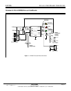
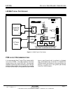
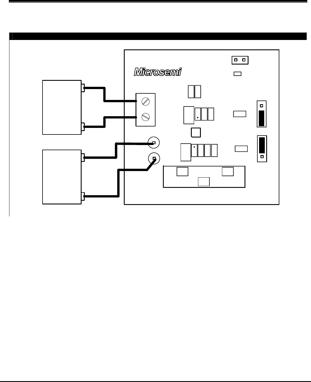
LX2206 TYPICAL TEST HOOKUP
I PGM
3
R7
BAT+
RTN
R8
R9
R10
R1
1
1
3
BATTERY
3
SHUTDOWN
GND
PWR
R3
R2
C2
R4
R6
313
CHARGING
1
C1
INTEGRATED PRODUCTS
1
RTN
OFF
ON
C3
LX2206
RT1
FULL
R5
1
L
H
13
ATTACHED
POWER
BAT TEMP
NTC
STATUS
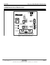
LX2206 DUAL LEVEL LITHIUM-ION
BATTERY CHARGER EVAL PCB
Single Cell
Lithium Ion
Battery
-
+
5V Power
Supply
+
-
Figure 3 – LX2206 Typical Test Hookup
PCB
LAYOUT RECOMMENDATIONS
It is recommended that C1 and C2 be located within
1cm of the LX2206. The CMP capacitor should be
located close to the IN and CMP pins. Also the high
impedance summing node connecting to the TMP pin
should be kept relatively short to prevent the coupling
of noise into this node. It is important that the LX2206
have a good thermal path to ambient to dissipate
heat. The simplest way to do this is to heatsink the
LX2206 bottom pad directly to the ground plane by
placing 4 or more vias in the ground pad directly
under the LX2206 footprint.