


13
(
You can also use an
y
3mm diameter tool,
such as a hex wrench or drill bit for this
purpose.)
9. Insert the screws for the first gib, turning
them with the T-handle wrench. Do not fully
tighten the screws; make them only snug
enough to hold the knife in the groove.
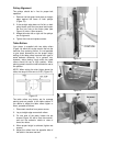
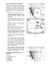
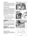
10. Put the next gib in place, and repeat the
process. See Figure 19. Use the adjustment
pins and make sure the wings of the knife
are completely in the cutterhead groove.
Continue sequentially from one end of the
cutterhead to the other end. Again, only
make the screws snug enough to hold the
knife in the groove.
11. When all gibs are loosely installed for one
knife, rotate the cutterhead and repeat the
process for each of the remaining two
knives, working from one end to the other.
12. Now fully tighten all gib screws on one knife.
Do this in sequential order, beginning at one
end of the knife and working your way
across to the other end, tightening each
screw in turn.
13. Tighten all gib screws on the other two
knives in the same fashion, until all gib
screws on the cutterhead are firmly
tightened.
(NOTE: The purpose of this incremental
tightening process is to prevent any slight
deflection or warpage of the cutterhead, and
to ensure that the knife is completely seated
into the groove.)
After installing knives, check
again carefully. Make certain all gib screws
are tightened securely. Failure to heed may
result in personal injury.
14. Re-install chip deflector (see “Chip
Deflector”, page 17). Re-install cover with
the four washer head screws, and re-install
belt guard.
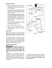
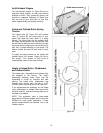
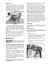
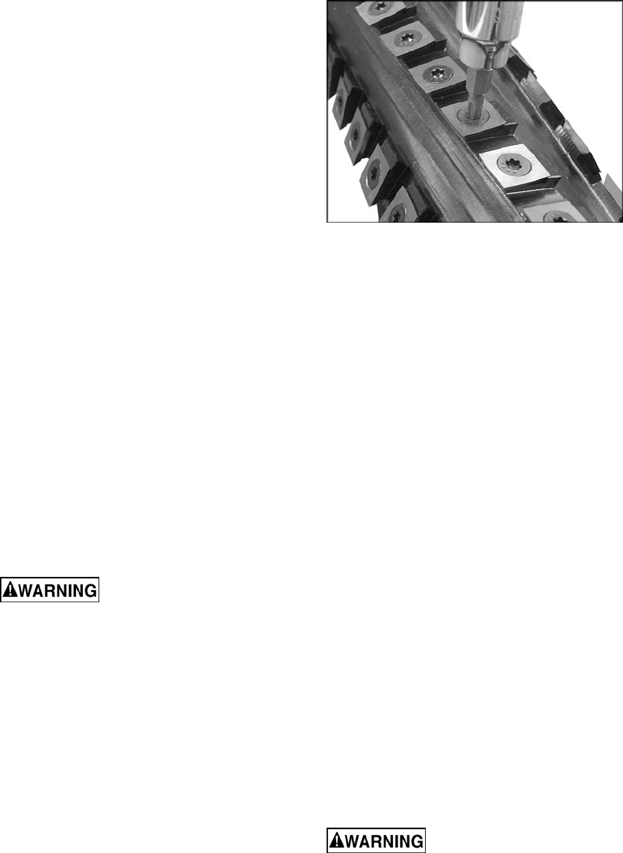
Replacing or Rotating Knife Inserts
(Model 15HH only)
The knife inserts on the model 15HH are four-
sided. When dull, simply remove each insert,
rotate it 90° for a fresh edge, and re-install it.
Use the provided driver with the socket adaptor
to remove the knife insert screw. See Figure 20.
NOTE: A T25 adaptor or driver can round out
the screw head. Always use a T25-Plus driver
or adaptor.
Figure 20 – Model 15HH only
It is advisable to rotate all inserts at the same
time to maintain consistent cutting. However, if
one or more knife inserts develops a nick, rotate
only those inserts that are affected.
Each knife insert has an etched reference mark
so you can keep track of the rotations.
IMPORTANT: When removing or rotating
inserts, clean saw dust from the screw, the
insert, and the cutterhead platform. Dust
accumulation between these elements can
prevent the insert from seating properly, and
may affect the quality of the cut.
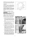
To install new knife inserts:
1. Before installing each screw, lightly coat the
screw threads with machine oil and wipe off
any excess.
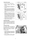
2. Position knife insert and move it back and
forth to verify there are no burrs or dirt.
3. Hold insert away from the back of the seat
(pull slightly toward yourself if facing the
cutting edge) and allow the screw to pull
insert into position. Note: A slight offset
between screw hole and hole in knife insert
is normal. Do not position insert directly over
screw hole, as it could ride up on the back of
the seat and potentially cause cracking of
the tip.
4. Securely tighten each screw which holds the
knife inserts before operating the planer.
IMPORTANT: Maximum torque for tightening
the screws is 45 to 55 inch pounds (3.75 to 4.6
foot pounds).
Make sure all knife insert
screws are tightened securely. Loose inserts
can be propelled at high speed from a
rotating cutterhead, causing injury.