


21
From this point on, any table movement will be
based off this setting. The setting will be kept in
the device’s memory even when the digital
display is turned off, and only needs re-setting
after a battery has lost charge and needs
replacing.
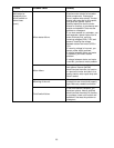
TOL – tolerance setting
This function is not generally used in planer
operations, but is here explained for reference.
Press TOL, and an up-arrow indicator will
appear, as well as a flashing “SET” indicator.
You can now change the upper tolerance limit.
Hold down the TOL button and each digit
flashes in turn. When the digit you want flashes,
release the TOL button.
Press TOL button once (no longer than 1
second) and that digit will increase each time
TOL is pressed.
When finished, press and hold TOL button until
indicator “SET” flashes. While indicator “SET” is
flashing, press SET button to change the arrow
to the down-arrow indicator. You can now
change the lower tolerance limit in the same
manner as you changed the upper tolerance
limit.
When finished setting the lower tolerance limit,
while indicator “SET” is flashing, press SET
button (no longer than 1 second). The device is
now in tolerance measuring mode. When the up-
arrow indicator is displayed, it means the
measured value is beyond the upper limit. When
the down-arrow indicator is displayed, the
measured value is below the lower limit. When
the display shows an “OK” indicator, the
measured value is within tolerance.
Calibrating & Using Digital
Scale
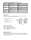
Scale Alignment
The scale assembly has been mounted and
aligned with the 15S Planer table at the factory.
The scale should be in vertical position, and the
digital device should slide smoothly along the full
length of the scale. Check occasionally that the
screws holding the device to the planer are tight.
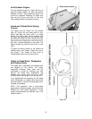
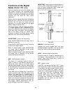
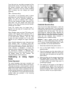
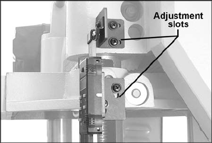
If any realignment of the scale should ever be
needed, slots are provided in the mounting
brackets (Fig. 41).
Figure 41
Establish Absolute Zero
One of your first steps should be to “zero” the
digital scale in absolute mode. This is equivalent
to finding the exact point of contact between the
cutterhead knife and the table. This can’t be
done simply by raising the table, because the
depth limiter on the head casting will prevent
contact between table and cutterhead. However,
there are two relatively easy methods of
establishing zero in absolute mode:
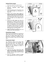
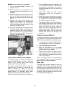
Method 1 uses a gauge, such as a height
gauge, or a home-made gauge block (see Fig.
17). If using a home-made gauge block, make
sure it has been cut to exact specifications.
1. Disconnect machine from power source.
2. Turn on the digital display. It turns on in
absolute mode.
3. Place the gauge upon the planer table and
under the cutterhead. (Make sure the gauge
lies solidly upon the table and not upon the
table rollers.)
4. Raise the table until the gauge just touches
the lowest point of a knife. Rock the
cutterhead slightly (use the pulley to do this)
to make certain the knife’s high point is
contacting the gauge.
5. The reading on the gauge, or the height of
the gauge block, should now be input into
the digital display. Refer to the instructions
above involving the “SET” button function to
input this number into your digital display.